M3KXZ'S TRI-BAND VERTICAL MOXON
Editor's Note: Fresh off his success with his beach mounted vertical Moxon, Pete Millis, M3KXZ, started thinking about multi-banding. The MoxonProject website has several multiband Moxon designs each of which is unique and approaches the subject from differing perspectives. Pete's design follows in this tradition. Shown below are a series of emails and MessageBoard postings sent between Pete, Allen Baker KG4JJH, and your humble webmaster.
4/28/2006:
Hi Steve.
Just a quick update for you.
I have now come up with a design for a tri-band "Moxon" that doesn't suffer from the effects of interaction between elements. Cebik shows a design for the "simplest 17-12 Moxon" (<http://www.cebik.com/moxon/1712m.html>), but this does not have the close end coupling between driven element and 12m reflector. He also discusses the problem of making a Moxon work on consecutive bands and suggest skipping a band to minimise interaction between elements.
The design I have come up with uses a "non-resonant on the ham bands" driven element (an EDZ). I want to operate on 20, 17 and 15 on one antenna. The EDZ is therefore only about 67% the length required for the full size 20m driven element. This has enabled me to shorten the entire vertical dimension as I have reduced the folded back section on the driven element and lengthened the folded section on the 20m reflector.
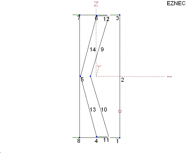
I have incorporated reflectors for 17m and 15m inside the perimeter of 20m antenna. But instead of doing what Cebik and others have done (i.e have the straight reflector section and then ends folded forward - which in the case of Cebik's design mean that the ends of this reflector are no longer close couple to the ends of the driven element), I have done something different. Based on the idea that close end coupling is very important, I have put the ends close together, but then set the element up as a "V". This sets a good distance between centre of driven element and centre of reflector.
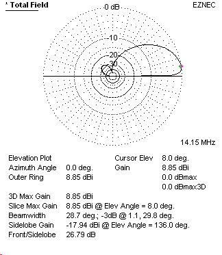
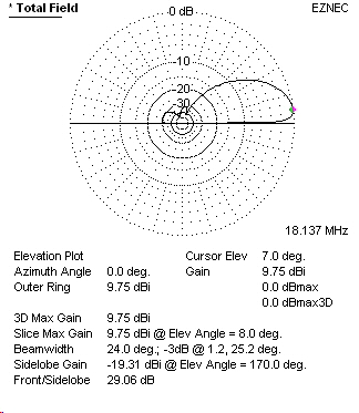
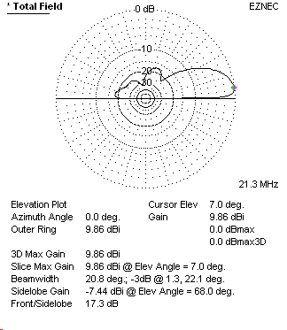
It's hard to explain in words, so I've attached the .EZ file for you to look at. Have a look at the patterns if you get a chance. The modeled F/B ratio and gain is superb. (DOWNLOAD EZNEC FILE HERE)
Another enhancement has been to move the feedpoint closer to the ground to make setting up easier. I will be connecting my 4:1 balun (the W1CG design) and tuner here. Shifting the feedpoint like this has very little effect on performance of the antenna, but makes the practicalities more straightforward.
I know in some ways this is a more complicated set up (i.e. it requires a tuner) but the performance should be far batter than a fully nested Moxon.
Interested to know what you think. I am working on getting this built this weekend and tested during the week. My modeling has been checked by another ham and all seems to be good.
Kind regards
Pete Millis, M3KXZ
4/29/2006:
Hi Steve and Allen.High SWR's don't so much affect the radiating efficiency of an antenna, but they do cause increased transmission line losses when fed with coax. For this application, I am using a highly efficient 4:1 balun (the design by Charles Greene W1CG) at, or very close to, the feedpoint, and using my Elecraft T1 atu to tune close to 1:1 - then coax to the rig. This way, the losses are minimised.
Martin Gillen (VA3SIE) is also working on a vertical "Moxon" for 15 and 10. His initial design had a straight reflector for 10m, but we exchanged a couple of "you show me yours and I'll show you mine" emails, and he has now incorporated the "V" reflector as it greatly improves the F/B ratio.
Martin has been doing some very interesting stuff using a feedline optimisation program, and has calculated twinline feeder lengths that bring the SWR right down to below 2:1. This is something that I will probably adopt in the final build.
Forgot to mention - ignore the way the currents face in the model - these only show the magnitude of the current, and not the direction the antenna is firing in. This works in the usual way with driven element and reflectors.
5/4/2006 (via MoxonMessageBoard):
I have made a modification to my vertical beach Moxons - the feedpoint has now been moved down to just over a metre above the bottom corner of the driven element. This has been done purely from a practical point of view, and was necessary in helping me with development of my tri-bander (20/17/15).
A requirement for getting good performance from the tri-bander was to reduce the amount of wire within the perimeter of the Moxon. On L.B. Cebiks site there is a description of a simple dual band Moxon that has 2 nested reflectors and one "non-resonant on the ham bands" driven element. My tri-bander uses this sort of driven element but has better coupling between driven element and reflectors.
The reflector elements are all tuned for resonance on each of the ham bands. The driven element requires matching to the rig with a balun and atu. Due to the high SWR levels on such driven elements, it is important to keep the feed line between antenna and tuner as short as possible. By moving the feedpoint so it's not far above the ground, I can now mount the balun and the atu right there, thereby minimising transmissions line (TL) losses. The SWR on the TL between rig and tuner is close to 1:1 so even the use of very lightweight coax becomes acceptable for portable operation.
The EZNEC modeling of the antenna shows that very little difference in performance can be attributed to feedpoint location. Moving the feedpoint to a low point on vertical Moxon's is a useful proposition for anyone who wants an easier way to route the feedline away from the antenna. For a Moxon mounted above the ground, you could have the feedpoint at the bottom corner and drop the feedline down vertically, thereby getting rid of the problem of routing the feedline perpendicularly away from the centre of the antenna.
5/5/2006:
Hi Pete,
I took a look at your 20m Beach Moxon on the website. Very interesting and a great idea! I wish that I lived near the ocean to try your new Moxon application. I tried increasing the antenna height to see the effect. It appears that you have optimized the pattern and gain for a very low height above ground (salt water).
I have been very busy at work lately and haven't had much time to look at your tri-band version. I would be interested to learn how the testing is progressing. As Steve points out, the SWR does appear to be high, especially on 20m and less so on 15m. You are correct in that a good antenna tuner should be able to make this work. (I took a first look at the W1CG balun and made a note to try one.) However, I would be surprised if an autotuner will tune the 20m band. Most are limited to 10:1 SWR.
OK, I just reread your first email about using optimized twin-line lengths to get the SWR down to 2:1. Very good, sounds like you have covered all the bases.
Keep us posted.
73,Allen, KG4JJH
===
Hi Allen.
Thanks for your email.
I built 2 of the tri-band Moxons over the past couple of days. The first built from quite heavy wire (1.3mm core + 0.85mm insulation) doesn't pack quite as small as I wanted for portable. So the second I built yesterday is made form computer ribbon cable wire (.32mm core and .45mm insulation). I remodeled the new wire in EZNEC and found it necessary to very slightly shorten the tuning tails on 20m reflector and the 15m reflector.
As noted, the SWR is high on 20 and 15m, but the Elecraft T1 had no problem tuning to below 1.5:1 via the W1CG balun. I still haven't gone through the process of optimising feedline lengths as I felt that, provided the balun and tuner could handle it, the shorter the feedline between antenna and tuner the better. As such, I have just 50cm of feedline from antenna feedpoint to balun, and 20cm of coax from balun to tuner. This way, even though the SWR is high on the coax, the calculated losses really are minimal.
For construction, I used small offcuts of plastic damp proof coarse (the stuff used over here to stop damp creeping up walls when houses are built). This is really strong plastic sheet, which is easy to cut and holes can be made in it with a soldering iron. These are used at the points where the "<" shape wires connect to the "[" shape wire, and do a good job of holding things where they should be. Also, being plastic sheet it is also very light and easy to stash away.
The Moxon was just suspended at 4 corners using lengths of shock cord, and the fishing poles were angled away from each other on their ground stakes to enable sufficient tension to be applied across the top. There was no need for guying which is handy.
Putting the feedpoint low down has really helped with the practical aspects of it all, and it really has next to no impact on performance or radiation pattern.
In the early part of next week, I'll be setting up on the beach down here (lovely weather at the moment, which I hope continues to Monday!) and will be sure to sort out some pictures.
As soon as I have some more pictures and test results, you and Steve will be first to know.
BTW, Mr Cebik has showed an interest as well, so it may even make an appearance on his site at some point (never know!).
Cheers for now, and keep busy
Pete Millis