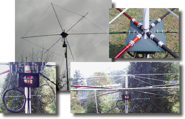
N0KHQ's Coaxial MOXON
The driven element and the reflector are the same size electrically. There is a 270 deg phasing line running from the driven element to the reflector. The feed line (2) paralleled 1/4 wave 75ohm pieces of coax interrupt the phasing line at 1/4 wave. The little black box (bottom left photo) is the termination point for the feed line and the phasing lines (one 1/4 wave (rear element) and one 1/2 wave (front element))
Notes:
The distance between the driven element and reflector is 7 feet.
The fiber glass rods ended up being 7'4" long. The elements front and rear are 8' long each (4).
This design will resonate at 18.130 MHz at 9 feet height. When raised to 34 feet, the antenna should still resonate at 18.130. In the event that it resonates higher than 18.130, just add short pieces of wire to the tail sections of the driven element to adjust the frequency downward.
Builders of this antenna are encouraged to use an antenna analyzer such as the MFJ - 259B to properly adjust the antenna. (See antenna tuning procedure below)
Using RG-58U coax for the elements and taking advantage of the velocity factor results in a 38 percent reduction in the antennas overall size when compared to a MOXON with conventional wire elements.
The fiberglass poles (spreaders) only need to be 12' in length, discarding the final flimsy end sections.
An angle of 36 degrees was used for the pole spreaders with fiberglass garden stakes used to support the two dogbone insulators.
At the feed point to the phasing section John uses a T4-50ohm Current Balun form Radio Works. Because he is feeding the antenna in the phasing line, a balanced to unbalanced current balun is not required. John emphases that builders should use some sort of current balun with the MOXON to decouple the antenna from the coax shield.
Antenna element tuning procedure:
Using an MFJ 259B or better, connect a coaxial tee to the analyzer. On one side of the tee install a 50ohm termination resistor. The other side of the tee will be connected to the coax under test. For example, a 1/4 wave length piece of coax at resonance will show the following readings on the MFJ 259B:
49ohm
1:1 SWR
X=0 (or very close to it)
Next, cut a piece of RG-58/U PE VF.66 10' long. At one end of the coax trim back a couple of inches of the PVC jacket and separate the shield from the center conductor. This end will feed into the other side of the coaxial tee (center to center and shield to ground) on the MFJ. At the other end of the coax, remove a couple of inches of the PVC jacket, slide the shield back, strip 1" of the PE from the center conductor and short the shield to the center conductor.
Then, turn the tune knob on the MFJ to 18.050. You will notice that the piece of coax is not resonate. Turn the tune knob slowly down in frequency until the display reads 49ohm, 1:1 SWR and X=0. You should end up somewhere around 16.200.
Use this formula to determine how much of the 10' piece of coax you will have to trim off.
In this example: 16.200/18.050 = .897. Take 10' x .897 = 8.970'. This is the length that your 10' piece of coax should be trimmed to resonate at 18.050. Check again with the MFJ and repeat as necessary.
When you have resonated your piece of coax, only the center conductor will be used at the feed point. The other end will remain shorted.
The end result should be an electrical 1/4 wave length with over a 30% reduction in size as compared with an conventional awg wire for antenna elements.
Performance:
John has been testing his Coaxial MOXON on a daily basis comparing it against his Sterba Curtain as a reference. He feels that this is a somewhat unfair test but the Sterba is the only other antenna that he has. The Sterba and the Moxon (at 30') seem to compare equally on receive.....the jury is still out on transmit.
The Moxon front to back appears to be good. Because John is feeding the front element and rear element 270 Degrees out of phase, he believes the gain of the antenna to be somewhere around 8db (not to be confused with dbi). All testing is being done with 100 watts output.
As we move into the winter months more accurate testing will be done and performance updates will be added to this page as they become available.
A Coaxial Moxon is soon to be published on the Hamuniverse.Com website, but will not include the phasing or feeding as discussed here.
Note: Click here to read John's evaluation of his Coaxial MOXON antenna's performance.
Email John at N0KHQ@aol.com for additional information about his Coaxial MOXON.