The Moxon rectangle, what matters?
Note: This is not all my own work. AA2NN has described the direction switching Moxon earlier. But the sensitivity analysis is mine and in anyway the idea of a loaded, tunable reflector seems to have disappeared nowadays and may need to be repeated and emphasised!Analysis
Since the late Les Moxon, G6XN, described the beam antennas with tight coupling (VK2ABQ variants) there has been a growing interest in the antenna type that later become known as the Moxon rectangle. In short, this family of antennas consist of a driven element and a reflector, the difference from normal two-element beams being that the ends of the wire elements are brought very close to each other, giving a much tighter coupling. The pattern of radiation also differs quite markedly from the two-element beam, mainly in three respects:
- A wide main lobe, about 100 degress from the 3 dB down points
- Two very, very deep nulls at about 120 degrees from the main lobe
- Overall very compressed backlobes, with F/B over >30 dB quite achievable
G6XN fed his square with parallell transmission line feeder in the 300-600 ohm range, which is impractible for many potential users. Later L.B. Cebik, W4RNL determined more precise dimensions for the aspect of the rectangle that changed the impedance to 50 ohms. He proposed the dimensions now widely acknowledged as the standard when building Moxons. These dimensions give a turning radius of about 70 % compared to full sized two-element beams and are optimized for
- Best F/B-ratio and
- about 50 impedance
No wonder this has become a popular antenna. But, when real wires and surroundings, not least the ground effect, come into play the situation changes somewhat. The remarkable F/B-ratio of over 30 dB, sometimes even over 40 dB! is only realistic in free space or if the antenna is many wavelengths above the conducting ground. The sharp nulls disappear at lower heights too.
If contemplating a Moxon for the short-wave frequencies then more than likely one cannot find a position for the antenna high enough to get a useful F/B of over 30 dB and the nulls are also obliterated. Another fact that enters is that the length of the reflector is also somewhat dependant on the height above ground level.
All in all, many of the finer features of the antenna are not available for the short-wave bands, so what we end up with is a beam antenna with a wide forward lobe, a wide rear lobe at about 25 dB F/B-ratio and a gain of 10-12 dBi (including ground reflections). And all this in an antenna that is smaller than a comparable two-element beam. It is still impressive.
The general assumption is that the Moxon must consist of two unequal lengths of wire - one driven element and one reflector, the latter slightly longer. The critical measurements are the length of the reflector wire and, claimed most critical, the distance between the folded ends between the driven element and reflector. These distances must be kept to within 1 cm or so, or the Moxon's pattern will deteriorate.
Simulations, however, show that this kind of precision is not necessary for the antenna's use on the short-wave bands:
- Starting with the last one - the distance between the ends - simulations clearly suggest that, while this dimension is of major importance a couple of centimeters off will not change the antenna in any significant practical way.
- The length of the reflector, while important, is better left identically the same as the driven element, and then tuned for best F/B-ratio.
With these two devices at hand the Moxon antenna is far more easily constructed as it relaxes some of the most critical constructional difficulties.
F/B-ratio
The Moxon can show very fine F/B-ratios indeed, above 40 dBs have been mentioned. However that figure is only achievable in practice if the antenna is in free space. It also depends critically on the wire lengths and diameter. Some of its reputation for being extremely sensitive undoubtedly stems from this kind of analysis.
But even under ideal conditions one can argue that a 40 dB F/B is not really what one wants. Take a look at the diagrams below, both are simulations of a Moxon antenna in free space. The first has a F/B of 40 dB, and the next one a mere 30 dB, but all of its lobes are confined within this. Isn't this really what one would want?
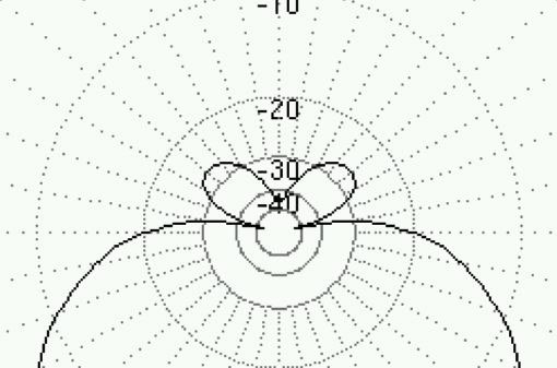
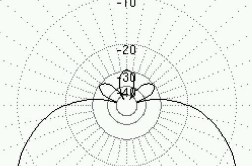
F/B-figures does not tell the whole story. The top diagram show an impressive 40 dB F/B-ratio but at the expense of less reduction in other angles. The lower picture, while not such impressive figures, is nevertheless more attractive.
Remember that the pictures above are in free space! A more realistic situation is a 14 MHz Moxon at at height of 10 meters (about half a wavelength):
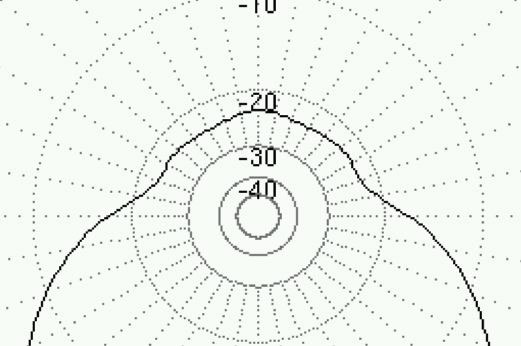
Expected radiation diagram under realistic situations for the short wave. The F/B-numbers in the 30-40 dB range are reduced to the 20-30 range. Still very acceptable performance.
Given the discussion above I conclude that for short-wave use, the most critical dimension of the Moxon, the space between the ends, is not all that critical after all. Precision within, say, 5 cm is sufficient. Extra precision is muddled up anyway due to the low height. What remains is how to make the construction perform at its maximum despite the unevitable error in cutting the wire lengths. This is attacked by making it easily adjustable.
Reflector length
Since not every installation is identical, and ones ability to construct the Moxon mechanically differs from person to person, the precalculated fixed lengths may not produce the best pattern, certainly not when it comes to F/B. People tend to take the antenna down to ground for restringing at least once before being satisfied with its performance. Whether they get it perfect immediately or just avoids the hassle of taking it down I don't know, but shortening or lengthening the reflector entails cumbersome cutting of wires (or worse, adding pieces of wire) and is a timeconsuming task.
I propose the use of a matching stub instead as indicated by AA2NN. The reflector needs to be loaded with some 60-70 ohms. Something which quite easily can be done with a "hairpin match" in the form of a piece of transmission line. The benefit is evident: No more cutting of wires, just trim the hairpin for best rejection of rearwards signals and you're done! It is much easier to trim the hairpin than to start fiddling with the wires again (and again, and again...). A drawback is perhaps having the hairpin hang from the antenna but it can be tied in direction of the centerpost so it doesn't fly around. Of course the hairpin must be adjusted while the antenna is in its proper position, but that is also true of the previous method.
Conclusion
The Moxon constructed the way described here has performance identical to the "standard" as long as the reflector is loaded with the correct amount. A direct benefit is that the two dipole elements can be made identical, which in turn makes a direction switching Moxon a realistic possiblity
Ideas and feedback are most welcome. Mail to
Michael has a wonderful website at http://www.isy.liu.se/~mj/HAM/ANT where he has posted many fine antenna construction notes.