![]()
![]()
![]()
![]()
![]()
![]()
![]()
![]()
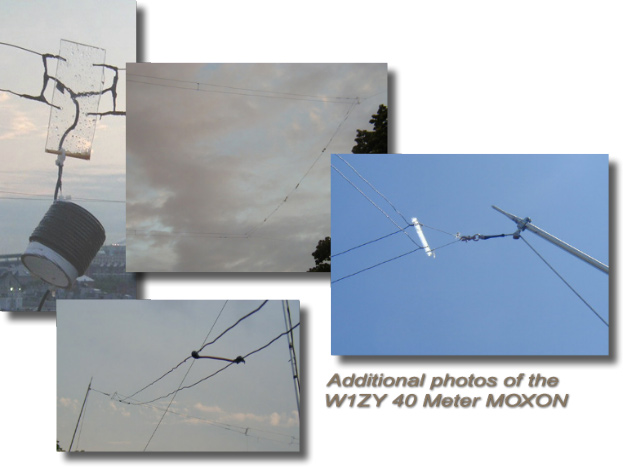
40 Meter MOXON
W1ZY's "Bill" 40 Meter MOXON is the product of 9 months of experimentation in 2003, requiring the construction of three prototypes. The final array is reversible and constructed from No. 12 insulated wire (Home Depot: $20/500') fed through two (2) RF current baluns (Palomar: $7.50/ea.).
The First Prototype: April, 2003
7.050 Mhz Single-wire, Non-switchable Moxon
No. 14 bare copper wire
A= 50.98'
B= 7.87'
C= 1.25'
D= 9.3'
E= 18.42
The first prototype was single wire and resonated for 7.050 Mhz--optimized for CW operation, but also enabling coverage into the European phone band. This array was not switchable. It was orientated NE/SW 75' above Boston Harbor. One end was suspended from its two corners by two mason lines cast over either side of a maple tree. The other side was suspended from its corners from two 10' poles mounted on the top of a 5 storey building. The array was fed through a simple RF current choke formed by 12 turns of coax wound around a 4" PVC tube. The tube was suspended directly beneath the array's single feed point.
What was interesting about this array was that the wires were doubled throughout the elements. No. 14 wire spaced 3" apart was used. The wires in the Driven Element were connected to each other at the feed point, as well as at the end of the element tips. Four (4) jumper wires (No. 8 bare solid copper) were added between these two endpoints. This was done to assure even current distribution between the two No. 14 wires, but also to serve as a means of physically maintaining the 3" separation between them. The first set of jumpers were placed 8' 6" from either side of the center feed point. The second set of jumpers were placed 8' 6" from the two corner insulators. No jumpers were placed in the tail end elements--primarily due to the fact that these spans of double-wire did not required mechanical reinforcement in order to maintain even separation.
The same jumper placement was incorporated within the reflector element. The center of the reflector naturally did not contain a feed point insulator. In its place a jumper wire was used.
All insulators used throughout the single-wire array had to be reconstructed in order to accommodate the two-wire scenario. This took a lot of thought and time. Sections of two 6' plexiglas semi-rods found in the garbage here in Boston were used. The rods are clear and measure about 3/4" in diameter. The fact that one side is flat eased accurate drilling of holes spaced 3" apart from one another to maintain proper wire separation.
The two-wire prototype requires four (4) corner insulators and four (4) tail-end insulators for a total of eight (8) two-wire insulators. This is in addition to the center feed point insulator. These insulators were constructed from 6" lengths of Plexiglas 'semi-rod.' Two holes were drilled 3" apart in the center of the rods. Two additional holes were drilled 1' from either end to accommodate two eyebolts. Between the two eyebolts a 1' rope 'handle' was secured. To this rope 'handle' stainless steel rope end-clips were connected. The end-clips, in turn, were secured to the ends of the four support ropes suspending the array. The clips/eyebolt system facilitated the ease with which the array could be taken down and hauled back up for the purposes of experimentation. However, this need not be necessary be part of a permanent installation.
A two-wire prototype requires pre-tensioning of all elements before final erection. This is undertaken in order to ensure that the two wires have equal tension between them so that they hang vertically with respect to one another. Too much tension on either the upper or lower wire will cause the pair to twist. Additionally, unequal tension between the two wires skews the corner and end insulators. Everything in the two-wire array should be squared up. This is accomplished by pre-tensioning the wires comprising all elements.
To achieve this, Bill strung up one end of each half-element to a vertical pipe about 3' above the roof. He then went to the other end of the half-element and secured one of its two wires through the insulator hole. The insulator was then held perfectly perpendicular to the wire and pulled tight. The second wire was then passed through its hole in the insulator and pulled until took up slack and sat perfectly beneath the first wire. The second wire was then secured to the insulator. We rechecked by pulling on the insulator--while the insulator was held perfectly vertical--to see whether or not both of the wires had equal amounts of tension and therefore sat vertically with respect to each other.
This was repeated for the other two-wire run from the center insulator to the corner insulator. It was then repeated for the runs between the corner and tail-end insulators. Once these runs had been pre-tensioned, the jumper wires were positioned and soldered into their respective positions. Once having done so, the two-wire elements are locked into position. This is why it is important to pre-=tension these elements before installing the jumper wires. If you do not do so, the jumper wires, corner insulators and tail end insulators will be skewed.
The same pre-tensioning exercise was performed on the reflector element. In this case Bill secured one corner insulator to the vertical pipe and then pulled on the other corner insulator, adjusting first one and then the
second wire.
It should be noted that the requirement of re-tensioning all eight (8) insulators in the two-wire prototype--in order to square it up--must be repeated every time the array is tuned during preliminary installation. Moreover, the tuning of the array's f/b ratio--derived from the ratio of tail-end (B) to parallel elements (A), as well as the gap (E) between element tips--affects the array's SWR curve. Thus an interplay between the two is in effect while tuning the array. Any of the adjustments made during the tuning stage require the physical re-tensioning of the wires as described. With eight (8) corner insulators accommodating the two, separate wires, this makes for a total of 16 individual wire-insulator points that require adjustment each time the array is lowered and tuned. To obviate some of this time-consuming work, we initially used cable ties to secure the wires through the corner insulator holes. Bill simply pulled both sides of the wire toward each other to secure it through the insulator hole. To adjust these points, he simply clipped off the cable tie, moved the wire and re-clamped it with another cable tie. When it came time to install the array in it permanent position, Bill removed the ties, stripped 1/2" of insulation from the wire on either side of the insulator and soldered into place a short wire which secured the wire placement through the insulator hole.
The tail ends were not tapered. They were butt-ended and formed by shorting out the two wires after each was secured to its respective hole within the tail-end insulator. This method was undertaken to facilitate extensive tuning of the two-wire array. During tuning, the tail-end jumpers were removed. We then added or subtracted wire from the array (via the tail-ends). After so doing, the tail-end jumpers were replaced and the array
re-hauled for testing. This method enabled Bill to adjust not only the tail-end dimensions, but the longer, parallel dimension by repositioning the corner insulators after adding or subtracting wire via the tail-ends. The alternative was to add or subtract wire from the center feed point. Bill opted to avoid this in order to obviate re-soldering of the feed point electrical connection as well as the prospect of introducing splices at this important juncture, as would be the case when additional wire was added to lengthen dimensions of the array.
NOTE: The preferred tail-end method was employed in the third prototype. In this case Bill had a good idea of the array's final, optimal dimensions due to construction of the two, previous prototypes. Armed with this foreknowledge, Bill was confident enough to use a contiguous length of wire when constructing each half-element. This enabled the removal of the tail-end jumper wires employed in the Second Prototype. In place of these jumpers, Bill passed the 'top' wire through the 'top' hole of a tail-end insulator, ran it down along the insulator's 3" length, and then exited out the 'bottom' hole of the insulator. The wire was then strung back beneath the 'top' wire, passing through the 'bottom' hole of the corner insulator and thereafter back through the 'bottom' hole of the center feed point insulator. Thus one piece of wire divorced of splices or end-jumpers--was used in the construction of each half-element in the third prototype design.
Bill recommends that first-time builders use jumper wires in the tail-ends in order to facilitate initial tuning of the array. When the tuning has been completed, the tail-end jumpers can be soldered into place and covered with silicone or some other type of weatherproofing material. The more ambitious builder can naturally dismantle the array and restring the half-elements using a single, contiguous length of wire. The choice is left up to the individual builder.
Click Soundbite to hear the difference in signal strength as Bill flipped his array back and forth on receive. There is 30 - 35 dB front to back, which means that in one position (NE) you hear Europe and in the other position you hear South America. One set of signals replaces the other.
Bill feels that many antenna tests which compare the MOXON against another antenna on TRANSMIT arguably do not fully capture the advantage of the MOXON. This advantage is the antenna's ability to radically reduce signals to its rear in the receive mode. Although, the MOXON provides about 5 or 6 dB increased signal strength on transmit, it's major unique characteristic is the 25 - 30 dB rejection off the rear and with only two wires.
With a "flippable" MOXON, you can start to see what this array can do in a manner which might be interesting to prospective builders.

Email W1ZY "Bill" at
bdesj@earthlink.net
for additional information
about his 40 meter MOXON.