k4QKY's MOXON
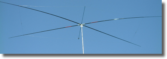
Completed MOXON at 30 ft. on a push-up mast
Materials
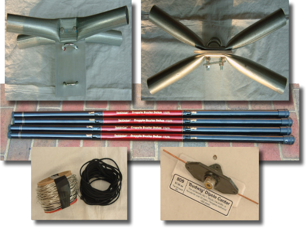
![]() Top left, above photo: Side view of the 3 piece pole bracket assembly. Note
the 4"X6.75"X.25" mast bracket plate which was cut from 6061-T6 aluminum stock
with 4 holes drilled to accept two 2 mast clamp U bolts and 2 other holes for
attaching the 2 pole holders. Click
here for additional construction details.
Top left, above photo: Side view of the 3 piece pole bracket assembly. Note
the 4"X6.75"X.25" mast bracket plate which was cut from 6061-T6 aluminum stock
with 4 holes drilled to accept two 2 mast clamp U bolts and 2 other holes for
attaching the 2 pole holders. Click
here for additional construction details.
![]() Top right, above photo: Top view of the 3 piece pole bracket assembly. The
two pole holders are made of 1.25 inch electrical conduit and were compressed
and bent to form the correct 45 deg angle between opposing poles. Each pole
holder extends outward 7.50" from the mast. Click
here for additional construction details.
Top right, above photo: Top view of the 3 piece pole bracket assembly. The
two pole holders are made of 1.25 inch electrical conduit and were compressed
and bent to form the correct 45 deg angle between opposing poles. Each pole
holder extends outward 7.50" from the mast. Click
here for additional construction details.
![]() Center, above photo: This unique compact antenna uses a supporting structure
made with four 16 foot telescoping fiberglass crappie fishing poles. Poles are
from Tackleplus, model name Crapple Buster Deluxe, model number 1200-16BW available
from www.catfishsupplyco.com.
Center, above photo: This unique compact antenna uses a supporting structure
made with four 16 foot telescoping fiberglass crappie fishing poles. Poles are
from Tackleplus, model name Crapple Buster Deluxe, model number 1200-16BW available
from www.catfishsupplyco.com.
![]() Left bottom, above photo: The antenna's two elements are made using 16
gauge tinned copper antenna wire. Dacron line is used to strengthen the
structure and to separate the ends of the driven element from the ends of the
reflector.
Left bottom, above photo: The antenna's two elements are made using 16
gauge tinned copper antenna wire. Dacron line is used to strengthen the
structure and to separate the ends of the driven element from the ends of the
reflector.
![]() Right bottom, above photo: Driven element feed point connector.
Right bottom, above photo: Driven element feed point connector.
![]() Not shown: Miscellaneous hardware, wire tie wraps, electrical tape, etc.
Not shown: Miscellaneous hardware, wire tie wraps, electrical tape, etc.
Assembly
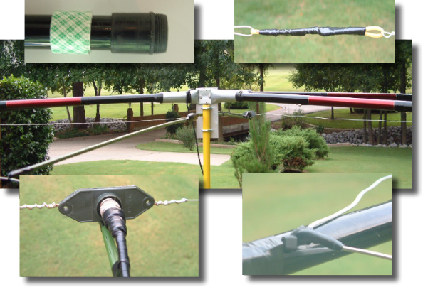
![]() Top left, above photo: Side view of the end of one of the four poles. Note
the ridge which had to be partially filed off in order to make it fit into the
end of the pole holders. Also note double sided tape (backing not removed) to
stabilize and cushion the pole in the pole holder.
Top left, above photo: Side view of the end of one of the four poles. Note
the ridge which had to be partially filed off in order to make it fit into the
end of the pole holders. Also note double sided tape (backing not removed) to
stabilize and cushion the pole in the pole holder.
![]() Top right, above photo: One of two insulators fashioned from nylon "weed
whacker" line.
Top right, above photo: One of two insulators fashioned from nylon "weed
whacker" line.
![]() Center, above photo: Assembled antenna temporarily mounted on a yellow
fiberglass pole for easy access. Note how each pole fits into the pole bracket
assembly. A green fiberglass "garden stake" runs from the center of the
reflector (extreme lower left corner) through a hole in the mast bracket to the
antenna feed point. Note: The
completed antenna remained over night 08/22/03 in it's temporary location shown
above. The antenna was entirely intact following a late night severe
thunder storm with 45 knot wind gusts attesting to it.
Center, above photo: Assembled antenna temporarily mounted on a yellow
fiberglass pole for easy access. Note how each pole fits into the pole bracket
assembly. A green fiberglass "garden stake" runs from the center of the
reflector (extreme lower left corner) through a hole in the mast bracket to the
antenna feed point. Note: The
completed antenna remained over night 08/22/03 in it's temporary location shown
above. The antenna was entirely intact following a late night severe
thunder storm with 45 knot wind gusts attesting to it.
![]() Left bottom, above photo: Driven element feed point assembly. Note green
fiberglass "garden stake" that supports the feed point and coax. It runs from
the center of the reflector (extreme lower left corner) through a hole in the
mast bracket to the antenna feed point.
Left bottom, above photo: Driven element feed point assembly. Note green
fiberglass "garden stake" that supports the feed point and coax. It runs from
the center of the reflector (extreme lower left corner) through a hole in the
mast bracket to the antenna feed point.
![]() Right bottom, above photo: Cable ties and electrical tape securing the
corners of each element to the pole spreaders. Note: The
completed antenna's flimsy construction presents some degree
of challenge in properly attaching the corners of the driven element and
reflector to the pole spreaders at equal distances.
Right bottom, above photo: Cable ties and electrical tape securing the
corners of each element to the pole spreaders. Note: The
completed antenna's flimsy construction presents some degree
of challenge in properly attaching the corners of the driven element and
reflector to the pole spreaders at equal distances.
Construction comments
![]() Isolation of the antenna from the push-up mast: The antenna was initially
attached directly to the mast as shown in the above photograph. However, upon
initial testing it was determined that the metallic mast and pole holders
severely detuned the antenna. To correct this problem, the antenna was
electrically isolated from the mast by the insertion of a 4 foot heavy duty
wooden broom handle (wrapped with electrical tape) 2 foot into the top section
of the push-up mast. The pole bracket assembly was then bolted to the top of
the broom handle. Subsequent SWR measurements indicate that the metallic pole
bracket itself may be the culprit. A non-metallic alternative pole bracket
assembly is currently being considered.
Isolation of the antenna from the push-up mast: The antenna was initially
attached directly to the mast as shown in the above photograph. However, upon
initial testing it was determined that the metallic mast and pole holders
severely detuned the antenna. To correct this problem, the antenna was
electrically isolated from the mast by the insertion of a 4 foot heavy duty
wooden broom handle (wrapped with electrical tape) 2 foot into the top section
of the push-up mast. The pole bracket assembly was then bolted to the top of
the broom handle. Subsequent SWR measurements indicate that the metallic pole
bracket itself may be the culprit. A non-metallic alternative pole bracket
assembly is currently being considered.
![]() Antenna dimensions calculated by the MoxGen program are generally valid:
Most builders of the MOXON will not find it necessary to lengthen or shorten any
of the wire lengths.
Antenna dimensions calculated by the MoxGen program are generally valid:
Most builders of the MOXON will not find it necessary to lengthen or shorten any
of the wire lengths.
![]() Difficulty making electrical tape stick to slippery poles. Electrical
tape was used to tape each pole joint as well as attaching the corners of each
wire element to the poles. Lightly sanding areas of the pole before taping
helps alleviate this problem.
Difficulty making electrical tape stick to slippery poles. Electrical
tape was used to tape each pole joint as well as attaching the corners of each
wire element to the poles. Lightly sanding areas of the pole before taping
helps alleviate this problem.
![]() The tradeoff to building a light weight antenna is reduced rigidity. The
antenna so light weight that it is easily rotated by hand. The ends of each
pole will naturally droop downward (like an umbrella) depending on the degree of
tension applied to the wire elements resulting from where they have been
attached to the poles. Employing a support pole from the center of the
reflector through the pole bracket assembly to the driven element feed point
helps stabilize the elements as well as the coax feed line.
The tradeoff to building a light weight antenna is reduced rigidity. The
antenna so light weight that it is easily rotated by hand. The ends of each
pole will naturally droop downward (like an umbrella) depending on the degree of
tension applied to the wire elements resulting from where they have been
attached to the poles. Employing a support pole from the center of the
reflector through the pole bracket assembly to the driven element feed point
helps stabilize the elements as well as the coax feed line.
Note: Click here to read Don's evaluation of his MOXON antenna's performance.
Email Don at k4qky@charter.net for additional information about his MOXON.