2E0RHM'S
Moxon Antenna for 433Mhz or 70cm Band

|
My 70cm antenna HB9CV was damaged beyond repair in heavy winds when it was smashed into several pieces. The best of intentions to replace it before a forthcoming contest went by the wayside and the sudden realisation that the contest was less than 24 hours away came as a shock. Despite several panic telephone calls I was left without an antenna for a 433Mhz contest which was due to take place. I was searching the internet for inspiration for a suitable portable yagi similar to a SOTA beam when I came across the Moxon project and details of a 70cm Moxon antenna. I investigated further looking closely at SM5JABís page on the project web site and also G3XBMís website, where both dealt in detail with the 70cm antenna. Deciding to have an attempt at producing one, I looked at an online moxon modeling calculator, entered the required figures and was surprised when the results came back with figures that were different than those given, either by SM5JAB or G3XMB. After considering all the options I decided to construct an antenna using the figures provided by SM5JAB with his measurements. The basic instructions and measurements were found on SM5JABís page on the Moxon Antenna Project website.
These dimensions will give almost 50 ohm at the feeding point. The gap of 17 millimetres is important for the radiation pattern. Generally speaking the dimensions should be followed quite accurately.Which - with a bit of luck - would result in these impressive figures:
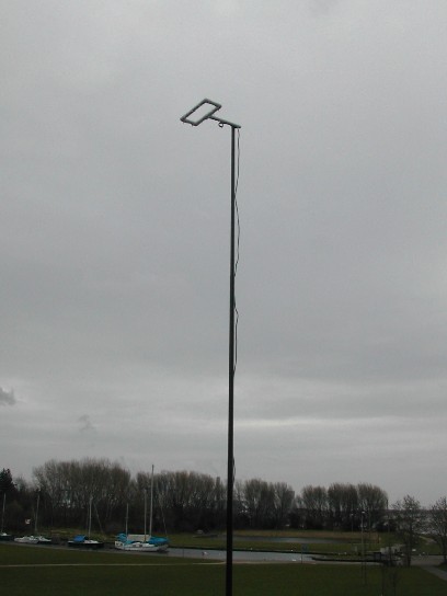
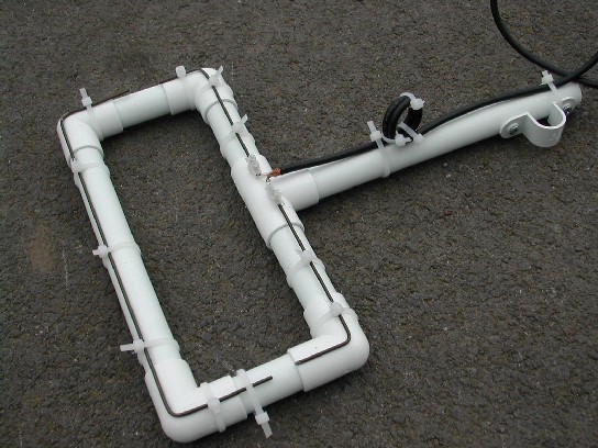
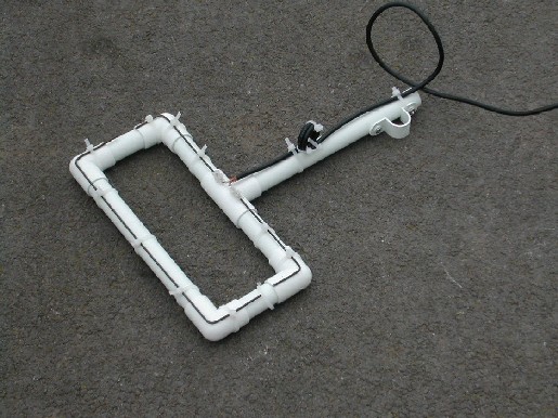
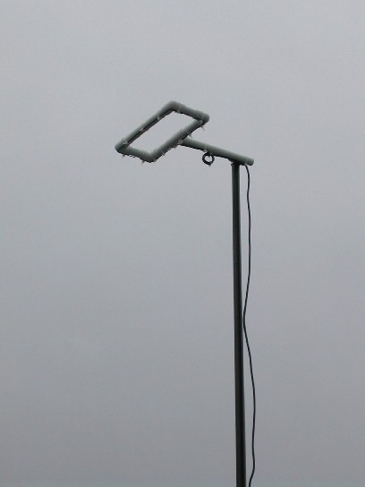
Acknowledgements to SM5JAB for above extract.Building The MoxonThe antenna was constructed on a support frame using 21.5mm plastic (pvc) water pipe. The driven element and the reflector were constructed of 2mm wire cut very carefully to the measurements shown then was fastened to the support frame using plastic cable ties. The antenna was very easy to manufacture although accurate measurements and bends were essential with the small sizes required for this frequency band. The most important measurement is the 17mm gap between the driven element and the reflector. As the wire opposite the driven element acts as a reflector the direction of maximum gain with this antenna is in the direction of the short boom used to fit the antenna to the mast, maximum gain being on the opposite side of the mast to the antenna itself. The total construction time, including the fiddling about with the frame was about 1 hour. The antenna was used in the 432Mhz contest on the day of its construction. I have to say, that I was very happy with the results, which far exceeded expectations, I had fifteen contacts within 1 hour 30 minutes, the furthest contact being over 120 miles. The prototype antenna, which I have pictured, is neat, compact and portable, and, the performance outstanding. I am now considering a similar antenna for 2m work. My thanks go to SM5JAB and G3XMB, for their guidance, inspiration and motivation. Bob Murphy 2E0RHM
|
visits: [an error occurred while processing this directive]


