Building the Moxon is fairly easy and lends itself to imagination. No two Moxon's are identical save the dimensions of the elements and spacings. If you view the various antennas in the What's New section on the homepage, you'll see what we mean. You can also view a variety of different hubs and designs here.
Since the Moxon is a 50 ohm antenna, you may or may not want to use a 1:1 balun. It's your choice. If you are planning on running any power, you might want to install a balun at the feedpoint. If you're not running any power, then feed the antenna directly from the coax (see Balun Notes below).
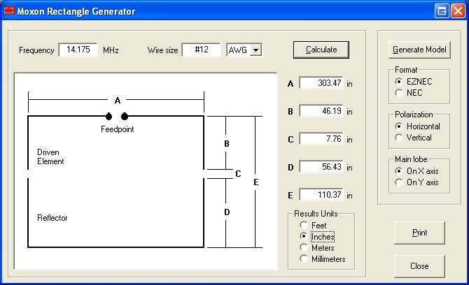
Once you've decided on what type of wire to use, and have used the Moxon Software to calculate the dimensions according to your band, you're ready to start constructing your Moxon. So, let's build one. Shown below are the dimensions for the 20 meter band.:
Here we've started the moxgen software, used 14.175 as center frequency, selected our #12AWG wire and hit calculate. The results are shown in inches, but you could have selected other units. You can even generate an eznec or nec antenna model (shown elsewhere on this website). So, looking at the diagram, we can see that the overall antenna will be 303.47 inches, or 25 feet long and just over 9 feet wide.
Sample Construction materials:
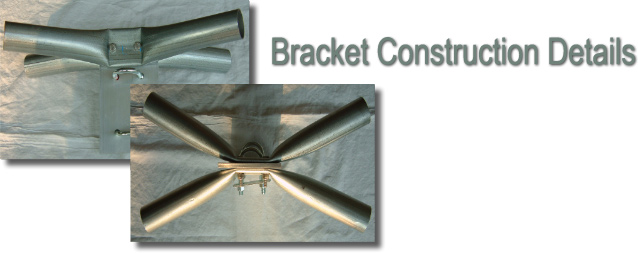
1 1/4 Inch conduit (for pole brackets)
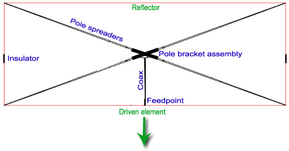
The pole bracket assembly was made by bending and flattening the conduit and inserting fiberglass crappie fishing poles as antenna spreaders into the open end..
But there are dozens of other ways using other materials to construct your hub as shown on this page and those below. If you have questions, visit the MoxonMessageBoard or email any of the hams listed on this site.
Individual antenna installations:
Balun Notes: The desired result at the antenna feedpoint is to make equal currents flow in the element on each side of the split. If the antenna is perfectly symmetrical and not close to anything, this will just happen, even with coaxial cable. You get equal and opposite currents at all times on the antenna element halves and in the coaxial cable conductors as well.(1) KD6WD "John", who was the original project organizer, has been experimenting with adding twenty meter capability to his MOXON. John is also contemplating the construction of a 40 meter version. John is in the process of relocating to Florida and expects to provide pictures of his MOXON after getting settled at his new QTH.
However, you can read John's evaluation of his MOXON by clicking here.
(2) K6SGH " Steve" initially suspended his MOXON beneath a tree. He also uses a balun at the feed point.
(3) K4QKY " Don" installed his MOXON on a simple 30 foot push-up mast.
(4) AB0YY "Ron" designed and built an alternative non-metallic pole bracket assembly for his MOXON.
(5) K6VYX " Martin" built his first MOXON with bamboo spreaders and a wooden hub. He has since replaced these spreaders with the same fiberglass poles used by the other project participants. Martin says that he much prefers fiberglass to bamboo.
(6) N0KHQ "John" in St. Louis believes that the antenna can be made using RG-58 coax to take advantage of the velocity factor .66 verses .95. He feels that using RG-58 would reduce the size, decrease noise and result in a 30% reduction in size. John designed and built a Coaxial MOXON which employs RG-58 coax instead of wire for the elements to reduce the physical size of the antenna.
(7) KF4EFH "Kevin" used Nylon cord for separation between the driven element and the reflector. Black plastic ties and electrical tape were used to hold the wire to the poles.
(8) G0WSP "Phil" designed and built a multi-band MOXON.
(9) Allen Baker "KG4JJH" wrote an article for the May, 2003 issue of QST magazine entitled The Black Widow--A Portable 15 Meter Beam... from MOXON to Cebik to Baker, a proven design that will have you reeling in contacts during Field Day and beyond.
(10) KA4SDU "Hal", maryannehal@hotmail.com designed and built his MOXON with bamboo but in a far different physical configuration. You can learn more about Hal's unique MOXON design by clicking here.
(11) W1ZY "Bill", bdesj@earthlink.net designed and built a 40 meter MOXON! It's a huge antenna! You can learn more about his antenna by clicking here.
Additionally, the following ham's have recently built MOXON antennas:
- N5GLR 20 meter hybrid Coaxial MOXON. Click here.
- F5MAG multi-band hybrid MOXON. Click here
- YU1QT 6 band hybrid MOXON. Click here. YU1QT has also built a 3 element 40 meter MOXON which you learn about by clicking here.
- W1ZY 40 meter MOXON. Click here.
- KA4SDU 17 meter Bamboo MOXON. Click here.
- 9Y4DD 20 meter MOXON. Click here.
Note: Click here to read MOXON antenna performance evaluations provided by several builders.
You can upset this balance by building the antenna asymmetrically or getting one side closer to the surrounding objects (trees, houses, other antennas) than others. If you upset this balance, then current may flow on the *outside* of the coaxial cable as if it were part of the antenna. This is a common situation, and is not the end of the world. However, the coax becomes part of your antenna, and the currents flowing on the shield affect the radiation pattern.
This can be a bit of an issue for highly directional antennas. The nice Moxon pattern will be changed by the coax. For better or worse, who knows. You might never notice.
With a properly designed choke or current balun, you can FORCE the currents on the element halves to be equal simply by making it "impossible" for them to flow on the coax shield. Such a balun could be a simple coil of coax (of the right diameter and number of turns) or a number of ferrite beads slipped over the outside of the coax (this is what I use).
If
you're not noticing any pattern problems (low front-to-back ratio) or
if those pattern problems don't bother you, don't worry about the
balun. If you are noticing pattern problems, put a balun on.
Such a balun can also keep electrical noise from the house from being
*conducted* onto the antenna by the coax shield. Sometimes an antenna
with a choke balun will be quieter than one without. The more
you care about your antenna's directional pattern (long boom yagis,
etc) the more you need to worry about making sure the feedline doesn't
become part of the antenna and radiate in unwanted directions.
Dan,
N3OX
www.n3ox.net