GSM1800 Moxon Square Antenna
by
Roberto Barrios, EB4EQA
-
If you are looking for an easy-to-build, ultra-cheap and good performance antenna to
extend the range of your GSM1800 band cellular telephone, you've come to the right place.
This little antenna works much better than the small tip found in most cell-phones (new Nokias
don't have the tip, but it beats them anyway...) and lets you use the phone where it was not possible before. There is only
one "but" with it: it's directional, and you'll have to play a bit until you find the right
direction to point to with it. If the available signal in your location is very weak, aiming
could get a bit critical, although not much because this antenna has a very wide front radiation
lobe. Forget about installing one in a car.
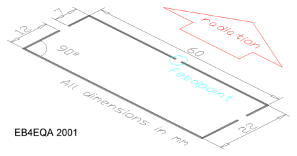
The antenna consists of three 1,5mm diameter copper wire pieces. One for the "reflector" and the other two for both sides of the "dipole". The Moxon square, basically a two element yagi, has the advantage of presenting a 50 ohms feedpoint impedance. Thus, it can be fed directly with 50-ohm coax. That means that you donīt have to build a folded dipole and 4:1 balum, gamma or T-match, which could easily have great attenuation at 1,8Ghz if they are not build accurately and with propper material. Purists would put ferrite cores on the coax as close to the feed point as possible to keep the RF coming back via the surface of the coax cable, but I've tried and haven't found any differences. The pieces of wire are so small and lightweight that they can be glued to a small plastic or wood boom (anything but a conductive material).
This is the construction plan for the antenna:

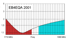
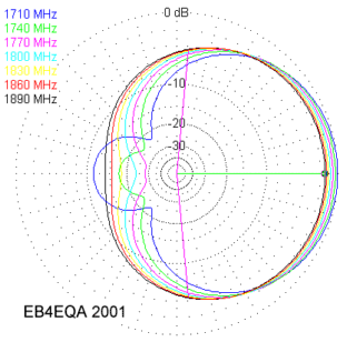
The expected SWR and radiation pattern for the GSM 1800 band are these:
|
|
You can see in the plot that the SWR does not get any higher than 2:1 on the entire GSM 1800 band.
I've divided the band in three zones: the red zone (1710-1785Mhz) is where the cell-phone transmits
and the blue one (1805-1880Mhz) is where the phone receives. The radiation diagram shows how the pattern
changes across the band. Anyway, the gain found in the main lobe is always around 5-6dBi, and the big
changes affect only to the back of the antenna.
You must be very careful when choosing the coax. This frequencies are so high that you could get an enormous
attenuation even with reasonable lengths of cable. If you use thin RG-174, don't use more than one meter. With
RG58 you could use a few more, but not many. Any cable thicker than that does not seem very practical to be
connected to a cellular phone. It is also advisable to keep connectors away, but if you need to use them, use
only N, SMA or BNC types. Never, never use a PL-259.
The way you connect the cable to the phone is something you'll have to think by yourself. You could use the
small antenna connector that most phones have, or you could just (as I've done) savage an old phone and connect
the coax directly to the RF PCB in the phone. This way, you can skip the connector and other circuitry found
at the antenna input, to keep the losses as low as possible.
To transmit, the cell-phone sites use panels with crossed polarization. That means that the orientation (vertical
or horizontal) of your antenna should not make any difference in the strength of the signal. I've written "should"
because I've noticed big changes in signal strenght when turning the antenna.
====
Roberto Barrios, EB4EQA has an EXCELLENT website where he has posted many interesting projects. Links to his homepage as well as Roberto's email are listed below. Clicking on his homepage link will launch a new browser window.
Roberto's HomePage: www.qsl.net/eb4eqa
EB4EQA email: rbarrioss@msn.com

