IK0GDH'S 40 METER LOADED MOXON
Let me say that this is a prototype and it is not a lightweight antenna. And, I would like to acknowledge the help of IO0MM, Luigi, without his knowledge of technical matters I could not have built this antenna, and IW0HKG, Massimo, who helped me during measurement (and a lot of patience).
The idea came when, surfing
the L.B. Cebik web site, I discovered the Moxon. I was really impressed:
high performance, reduced size. I needed a 40 mtrs beam but unfortunately,
at the moment I haven't enough room to host a full size antenna, even a
Moxon is too large. So why not further reduce the antenna adding inductors
along the elements? A German manufacturer has a kind of this on his
catalogue, the performance not so great as a full size beam but much more
than my home-made linear loaded rotary dipole. The MoxGen calculator doesn't
works with this design, step by step, attempt after attempt I did a model
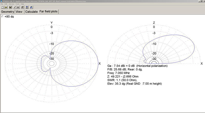
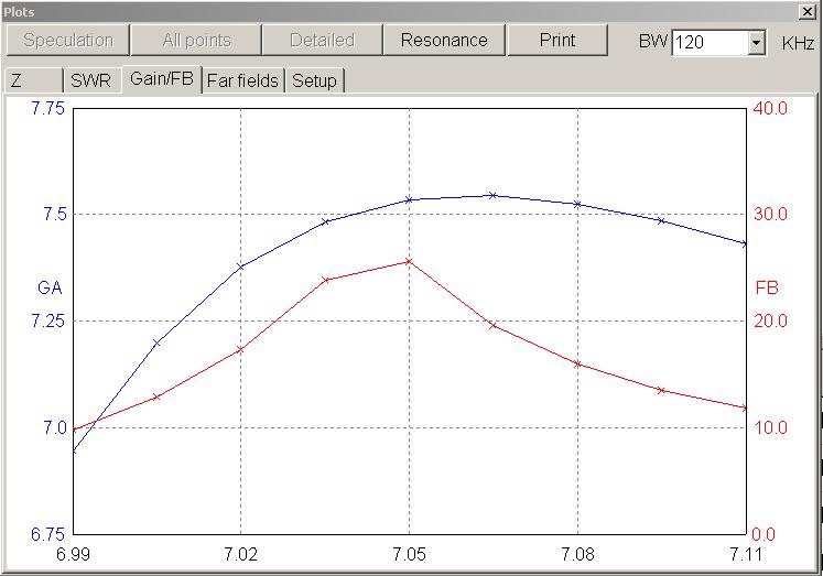
using MMANA modeling software. A theoretical gain of over 7 dbi and, most
importantly, a F/B Ratio of about 25 db along 50 Khz! Not too bad indeed.
I like to solve mechanical problems, mostly recycling materials and parts I
collect time to time. The idea was to use, for each half-dipole, aluminum
and copper wire supported by fiberglass poles to reduce weight (tnx to Andra
YU1QT for his suggestions). The inductors are self supporting air-wound
copper tube. Both director and reflector use the same type of stub tuning
method following the suggestions of SM5JAB, done to avoid to pull up and
down the antenna for tuning. The point where the feed line is connected slides
along the stub on the driven element, a shortening strap slides along on the other
stub on the reflector. I can remotely tune both the elements from the ground
level with the help of a pair of thin rope connected to the supports of the
sliding parts. Once optimized, all the moving parts will be replaced
by solid, fixed connections.
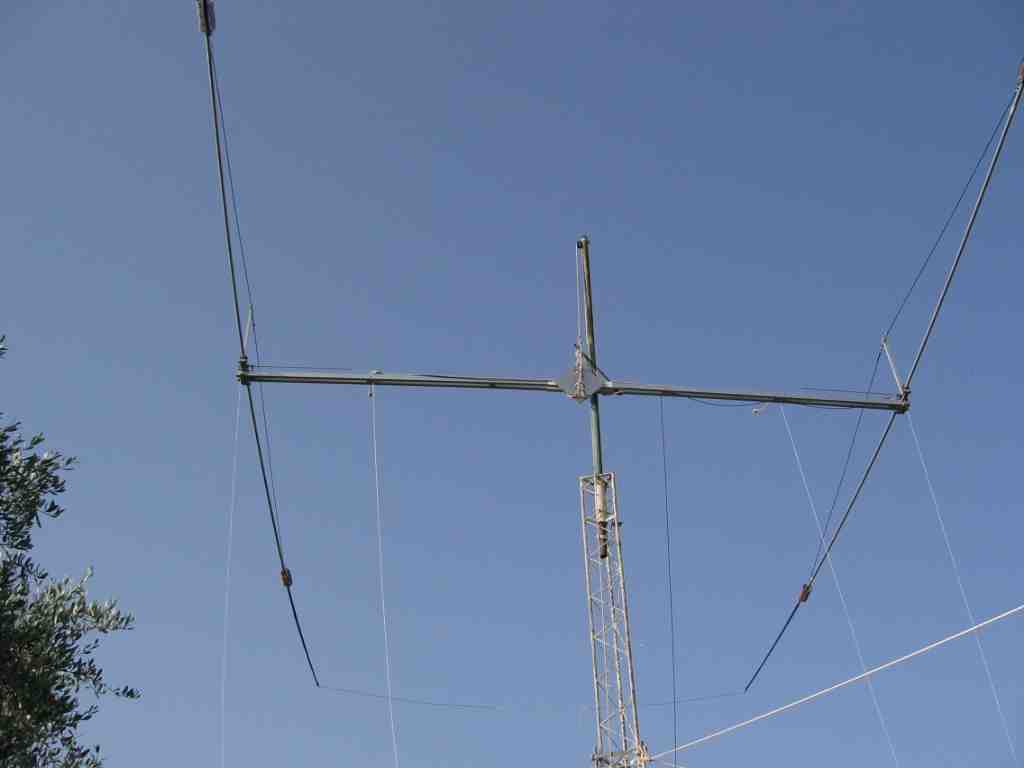
I erected the antenna on a 9 meter test tower at my mother's home. The trial began. With
only a few adjustments of the feed point on the driven stub, the
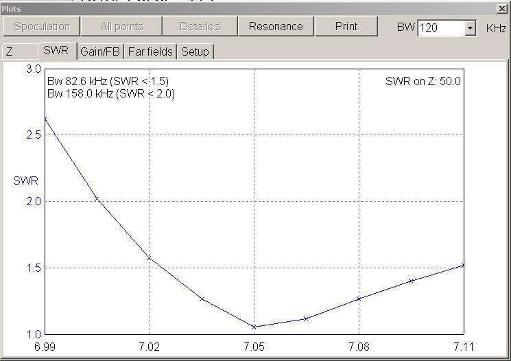
antenna analyzer showed a close to perfect match, with overall SWR less than 2:1 over 130
Khz! The same operation was performed to optimize the rear F/B.
PERFORMANCE
I put a full size reference dipole at the same height of the Moxon, about 15 mtrs away. Along the same radiating direction of the dipole, the Moxon won by 1 to 2 S points on receiving and about the same on transmitting. Signals from the rear dropped 2 to 6 S points vs. the dipole.
My next goals will be to further reduce the weight, changing the boom type, and so on. Game is not over.
40M Loaded Moxon Dimension and Construction notes:
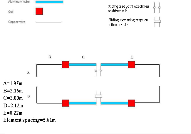
Antenna Summary (shown in inches)
|
Element spacing |
220.866 |
|
A |
77.559 |
|
B |
85.039 |
|
C |
118.110 |
|
D |
83.464 |
|
E |
8.661 |
|
Overall Length |
35.4 feet |
|
Width |
18.41 feet |
Construction:
Each half-element has been made with aluminum (outside diameter 30 mm) 3.0 meters long and fiberglass fishing pole 2.34 meters long. Aluminum and fiberglass are connected together with a DELRIN 0.33 meters long rod fitted inside. It serve also as a reinforcement of the fiberglass pole right where the coil is located. The diameter of the copper wire is 3 mm and it is coated with insulated material (FERTENE).
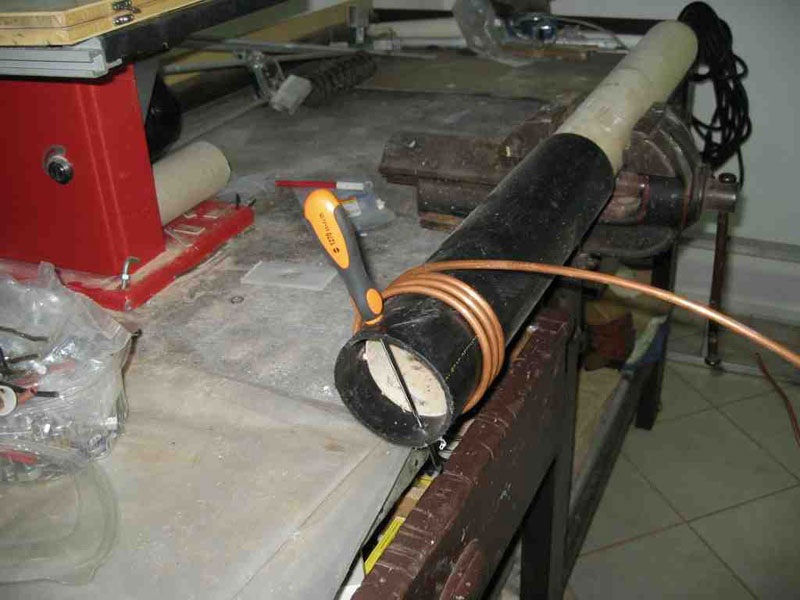
Both elements are insulated from boom. Each coil is abt 9.7 mH. with a theoretical Q of more than 800. I used a 6 mm copper tube. Turns spaced 6 mm aparts. 16 turns wrapped on 90 mm diameter. I home-made a simply machine to do the job, two pipes, one fitted into the other, the inner pipe with the same diameter of the coil can rotate, the outer is the "guide" and should be blocked on the workbench. A small hole in the inner pipe serve to block the start point of the wrap, you need two more holes few centimeters far away to insert across a long screwdriver or something like this to help to rotate the inner pipe. All done!
After the tuning trial, copper tube will be cleaned from oxide and painted with electrical insulating varnish to minimize parallel losses.
(About coils look at VE6WZ web site and to W8JI pages as well)
I used aluminum strap to connect the coil to the AL part of the element, it is 30 mm wide and surround the entire element tube. A small piece of wire is used for electrical redundancy. This point is the most important due to loss introduced by the connections. As you see in the pictures I used a pair of square aluminum rail for the boom but I realize that weight and wind surface area are too much. Next step will be a new rounded boom and new boom to elements plates. Works are still in progress!
Additional note: The sofware used to model the antenna is MMANA. It permits to fix the Z dimension (height) and to vary it "on the fly" adding more space without changing the base parameter. The antenna has been optimized for a total height of 15 meters. DOWNLOAD MMANA FILE HERE.
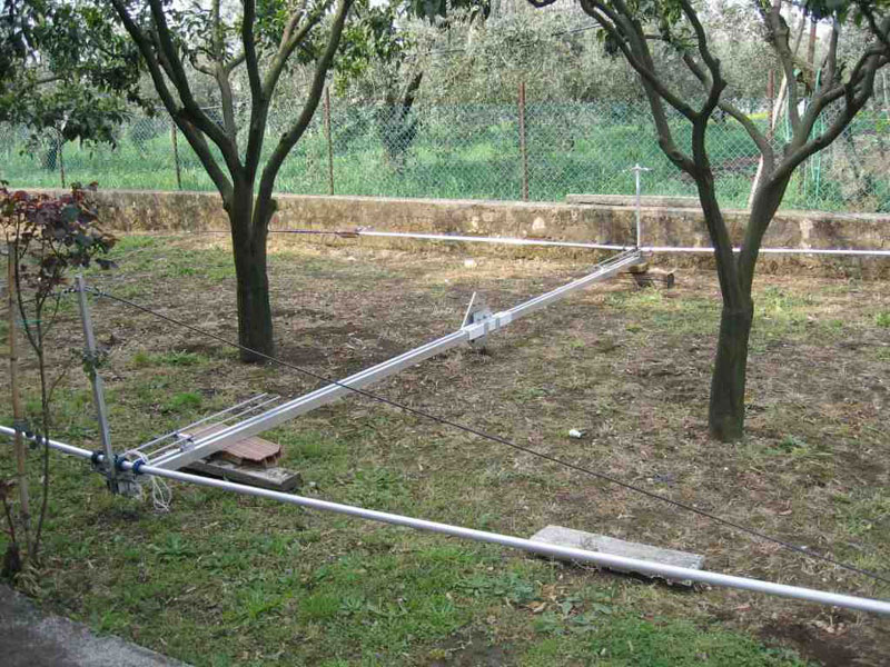
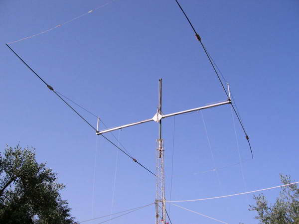
The broad views (above) show the antenna lying on ground trough the orange trees (where is my saw?). The white ropes pending from the antenna are parts of the "remote tuning system". And below you can see the feed line on the boom on the right. The element sags a bit which was modeled on MMANA.
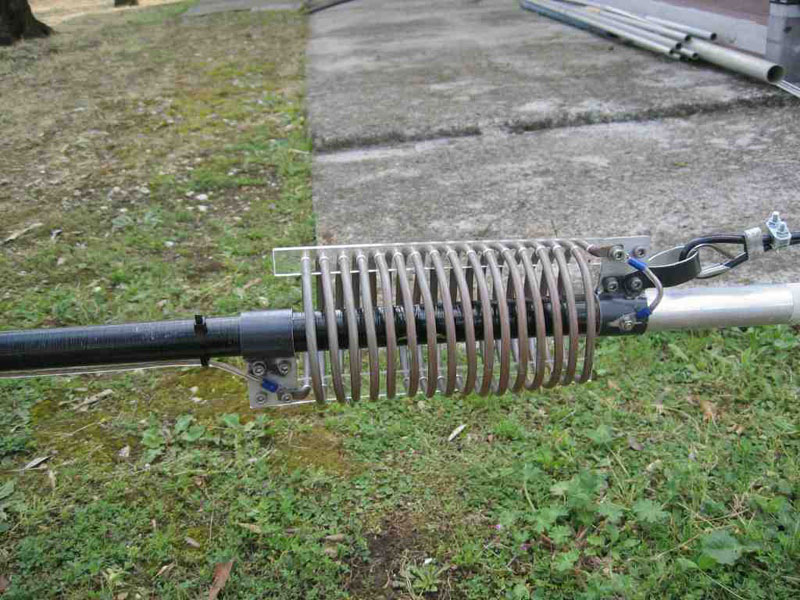
Mid element close-ups: You can see the aluminum element on the right, a jumper connection from to the coil, and the wire portion of the element on the left leaving the coil. Stefano used a plexiglas spacer to hold the coils in place.
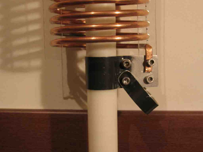
Particular of the coil and its strap. Note the point where the truss wire will be attached to support the element (and coil!) weight. I used a 6 mm Bayco as truss wire. No noticeable elements sag has been revealed.
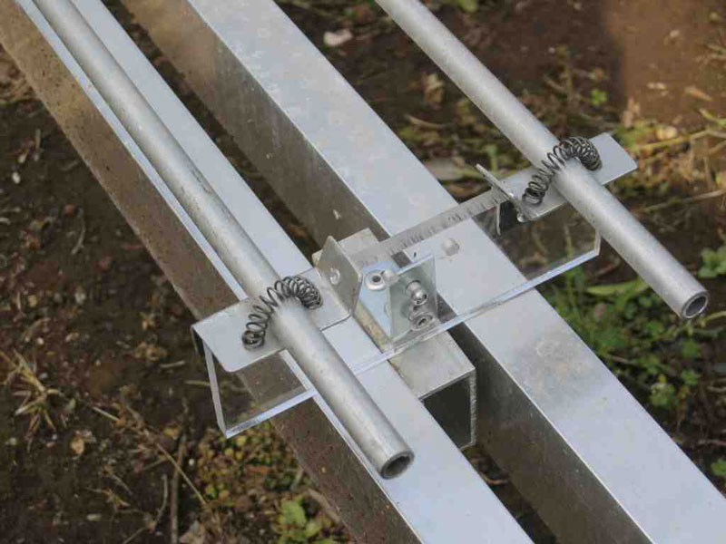
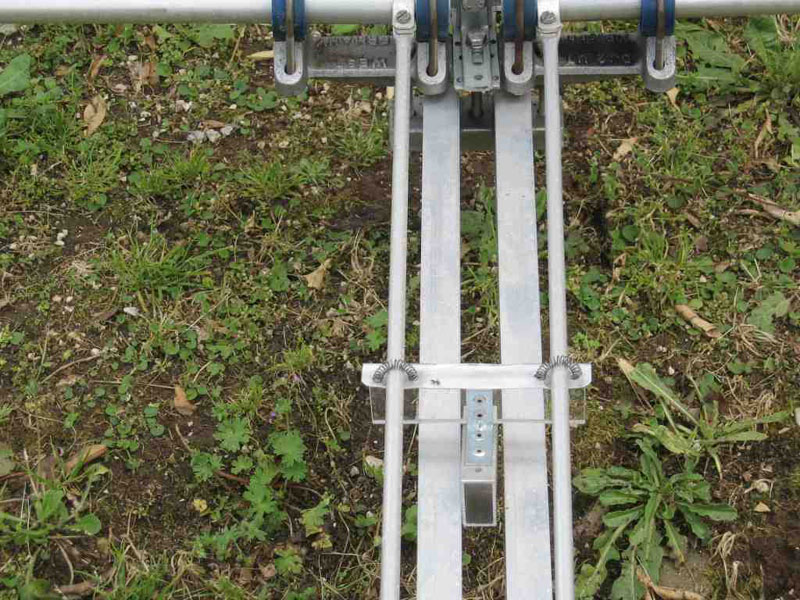
Two alloy strap mounted on insulated material, note the small holes where the feed line will be attached. Springs are used to maintain electrical contacts between parts while they slip during tuning operation. This system is for tuning purpose only. After tuning it will be replaced by a more convenient (and solid) system.
Here are the stub tuning portions of the driven element. You can see that the coax would connect to the terminals on the plexiglas. Ropes are added to slide the tuner back and forth along the aluminum stubs, the springs making the connection. These stubs are connected to the aluminum elements at the boom near the blue insulators.
.
fabrication of the tuning mechanism.
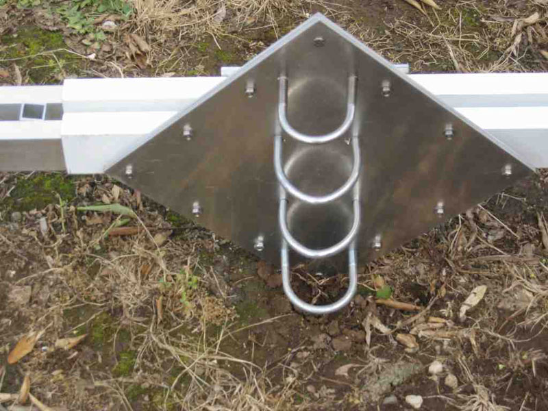
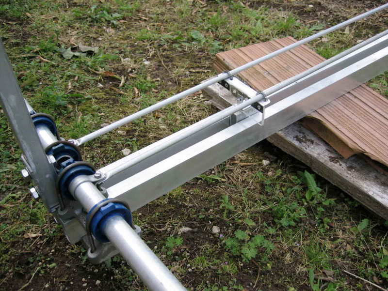
This shows how i built the boom to mast plate using 4 thin aluminum foils 2.5mm thick connected together with small bolts along the perimeter. Note the reinforcement of the boom at the attach point. I used a pair 2.5 X 5.00 cm.rails. I'm not quite satisfied of this boom, the plan is to change it with a traditional rounded boom to obtain less wind surface area and less weight.
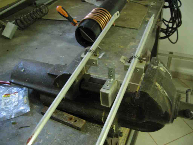
View of the reflector stub. The difference from the director stub is that I use a single AL strap to electrical short the contact.
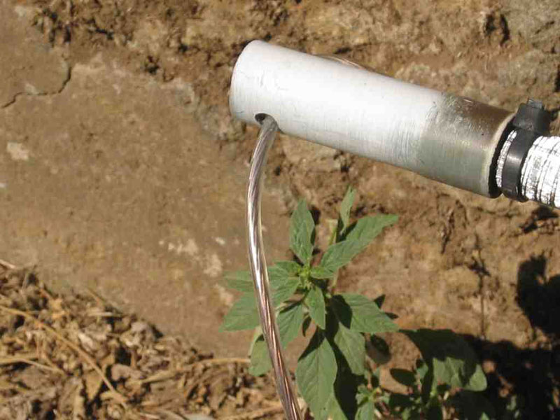
Each elements end are reinforced with a small PVC pipe where i made the hole for wire. Done to avoid stress on fiberglass. The wire part of the element run along the fiberglass (not inside!). Some plastic strap maintain the wire closed to the support.
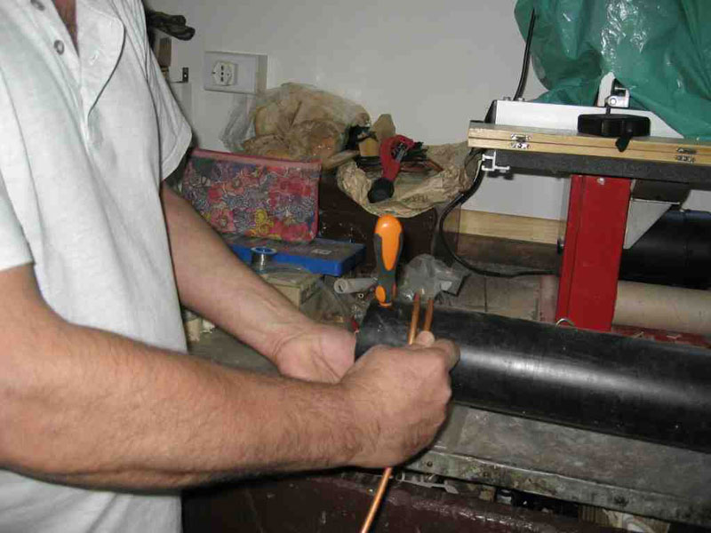
The art of coil winding.
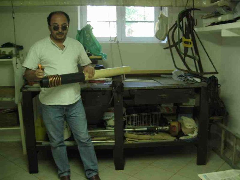
IK0GDH, Stefano, in his shop.
IK0GDH, Stefano, can be reached at this email address if you have questions about the construction of his superb antenna:
stefanop2 @ inwind.it
visits: [an error occurred while processing this directive]