N3OX'S DUAL BAND MOXON
17&20 Meters
When BS7H came up in May 2007, I knew I would need a better antenna to have a chance at working them from the East Coast. I had a 20m Moxon Rectangle stowed away in the shack that I had built very carefully and never put up. This article is not about the original construction of that antenna. There is plenty of good information on the mechanical construction of HF Moxon Rectangles using fiberglass fishing pole spreaders at the Moxon Antenna Project website. My spreader bracket is made of a plate of 6061 aluminum with four pieces of angle bolted to it that hold the 16 foot crappie poles from B'n'M.
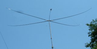
The finished antenna on a rotating mast.
It's a nice looking antenna, light, and works very well on 20m. I put it up temporarily for the BS7H operation, but it worked so much better than my delta loop that I wanted to put it up permanently. The delta loop, though, had a matching network to put it on 17m, and I neither wanted to give up 17 nor put up a separate antenna for it, so I decided to design a matching network. The first step was to take the 14MHz Moxon model and run it on 18.1MHz to get the feed impedance. Well, I looked at the model and noticed there was no significant current in the reflector on 17m. I decided to stick a load in the middle of the reflector and see if I could get some current and to see what the pattern was when I did so.
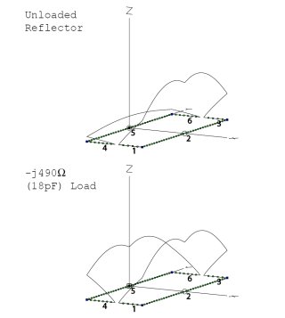
Element current distribution
This is the current distribution on the antenna without a load in the reflector compared to that with a -j490Ω load mid-reflector. I selected this load for optimum F/B at 18.1MHz over ground. A free space model shows a slightly different load to be optimum, maybe -j460Ω or so.
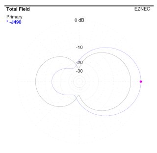
Free space pattern comparison on 17m.
These patterns are free space patterns for an antenna designed for 14.050MHz with AC6LA's Moxgen. Wire gauge is #18AWG (1mm). Free space gain of the antenna at 18.1MHz without the load in the reflector is about 3dBi, with just a few dB of F/B. With the load, the gain is a little over 6dBi and optimum 180 degree F/B is about 16-17dB. Not too shabby for adding a single capacitor. The impedance of the antenna is about 140+j500 Ω on 17m. Add a matching network to match that to 50 ohms, add some relays to switch between 17m and 20m, and we're done.
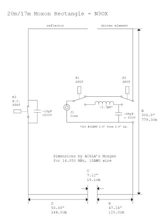
A schematic of the antenna with dimensions.
The schematic is also available as mox_schematic.pdf. There we have it, no fuss, no rats nest of wires, just a beam on an extra band with the addition of a few components. I'd recommend using a variable capacitor for the load and tweaking it if you want the best 17m performance.
It's important to note that the voltages across the capacitors on 17m are high. At 100W, we're looking at 350V across the 18pF reflector load capacitor and 475V across the 44pF L-network capacitor. At full legal power on 17m, these voltages are about 1400V and 1800V respectively! Also note that the relay in the reflector will need to stand off the same voltage as the capacitor. I think if you were going to build this antenna to take full legal limit, you probably want to use a vacuum relay there. Many relays would stand off 350V at 18.1MHz, so you can use all sorts of things at 100W. I used some tiny 3A rated telco relays I had laying around. For the reflector load I used a small ceramic trimmer. The L-network consists of a hand-wound coil and a small air variable. The reflector load is very light and so I just let the reflector support it.
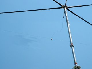
The reflector load and homebrew housing.
The relay and capacitor for the reflector are housed in a taped-together pair of black plastic caps from iced tea bottles. I wanted to be absolutely sure to decouple the DC power wire for the relay, so I used a good choke on the wire right at the reflector. I have some 3C8 material Ferroxcube pot cores and they have a big resistive component at 18MHz and work great for this. Lots of impedance and you don't have to worry about resonances as much. I didn't want to spend a lot of time tuning and tweaking this antenna, so I tried to eliminate as many confounding factors as I could. I didn't want a wire running from near the high-voltage feedpoint to near the high-voltage-at-a-different-phase reflector without some good chokes on it.
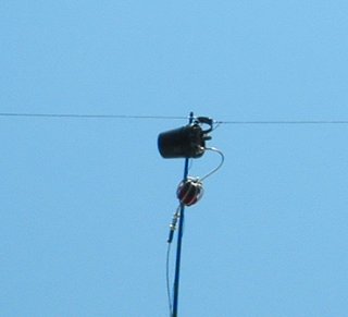
Feedpoint L-network and balun.
The L-network and the choke balun (eight turns of small diameter coax on a Fair-Rite suppression core) require an extra fiberglass support. Fortunately (?) I broke another fishing pole when I was putting up my rotatable flag antenna, so I had a couple of sections available as a support.
Through careful pre-tuning of the matching network into a lumped element RL load of 140+j500, I managed to get SWR under 2:1 across 17m with no further adjustment. SWR is a worse than usual indicator that the antenna is working, of course... it would actually have a similar SWR if it weren't operating as a beam, so I set up my MFJ-259B with a little whip antenna about 1.5 wavelengths away and checked the F/B with a step attenuator. The antenna is certainly directional and the 180 degree F/B is about 14dB; not as good as it could be, but this antenna is a little hard to get up and down in my small backyard, so I'm going to live with it for now.
This one is a pretty worthwhile modification. If you run 100W and have already built a 20m Moxon, it's a simple and cheap way to get on 17m as well. It eliminates the adjacent band problem that Cebik mentions in his Moxon pages. It would probably work for a 17/15m Moxon as well with suitable component changes. In fact, you could build a 20m/17m/15m tribander with equivalent performance on 17m and 15m if you used a -j950Ω (8pF) load for 15m. The issue there would be trying to match and load within reason... the feed impedance of the 20m Moxon used on 15m is 330+j1000Ω and the capacitor voltages for feedpoint/reflector are about 1000V/600V at **100W**!!
20m performance is totally unaffected by the additions with the exception of a small reliability hit due to the relays. I had some dirty-relay issues, I think, with some attendant signal dropouts, but I think that may have just been due to relay age and disuse. Cycling the relays a dozen times rapidly seems to have fixed it. I had originally designed an LC network for the reflector to automatically provide both a resonant short on 20m and a -j490Ω load on 17m, but the 20m performance took a hit over the width of the band, so I scrapped that idea before I got around to designing an auto-magical matching network as well... might be a possibility for a pair of narrow bands, though... 17m/12m might work out. Anyway, this antenna is at 30 feet providing a far superior replacement for my 20m/17m delta loop and I didn't have to lose 17m to get beam performance.
You can reach Dan at n3ox.dan@gmail.com and his website at www.n3ox.net
visits: [an error occurred while processing this directive]