The Moxon Rectangle
This is an intriguing antenna. Compared to a full-size 2 element yagi it is much smaller, yet gives comparable performance. This sounds great for shortwave, where antennas often get too large to be easily manageable.
I decided to make a small scale test of it. I have two very cheap PMR walkie-talkies. With a bit of solder they were converted to the LPD-band which overlaps the 70 cm amateur band. So the frequency in question was to be 433.5 MHz. A wavelength of 70 cm makes a nice modelling size compared to 15 metres!
The basic outline and dimensions were found on W4RN's excellent antenna site. Armed with these dimensions based on a 2 metre antenna, I used MMANA to scale the values for 433.5 MHz. Basically this is the same as cutting the figures in three but MMANA can be used to fine trim the dimensions. This is specially important here since the wire diametres start to be important at these frequencies. After a few iterations in MMANA I settled for these dimensions:
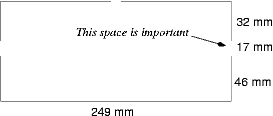
These dimensions will give almost 50 ohm at the feeding point. The gap of 17 millimetres is important for the radiation pattern. Generally speaking the dimensions should be followed quite accurately.
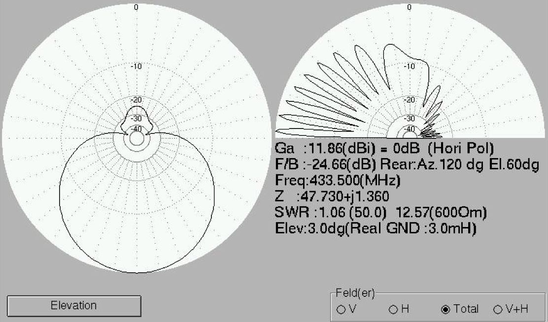
Which - with a bit of luck - would result in these impressive figures:
Building the Moxon
I wanted to make a wire model of the moxon. Two old coat hangers supplied the string needed. The diameter was 2 millimetres which was perfect. Easy to bend and cut.
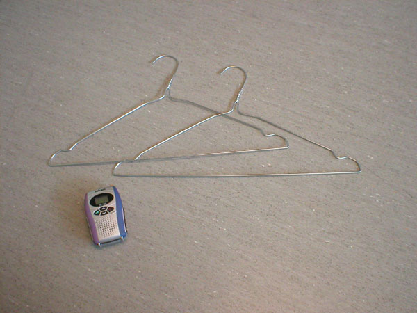
The antenna to be. Two hangers from the laundry supplied the metal wire. One of the radios is also seen in the picture. This beauty has an output of about 0.5 watt.
After some bending in the workshop the antenna took shape in less than an hour. The design is simple, only 90 degree bends are necessary. The dimensions are fairly critical at these frequencies and most important is the distance that separates the two halves. It should be accurate to within a millimetre. The other lengths do not require this kind of precision, but one should try to keep millimetre precision anyway.
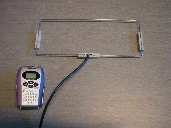
The complete moxon. After this shot was taken an attemt to create a balun was made at the coax connexion. A few beads of toroids was threaded to suppress unbalance currents. A handle was also attached for easier orientation when operating handheld. The upper wire works as a reflector so the direction of max gain is downwards in the figure.
Field tests
In the field tests show that the antenna possess gain and directivity. As the radio used does not have a signal strength meter no figures can be stated. It was however clear that a signal shifts between "clear and legible" to "covered in noise and hard to hear" when rotating the antenna.
According to the diagrams above there should be two sharp nulls in its radiation pattern, and... so there is. These nulls are razor sharp! I had no trouble pinpointing the direction of the transmitter with them. Hmm... perhaps this a direction finding antenna in sheep's clothing?
Field tests update
I have since used the moxon with a ICOM transceiver and found that the S-meter is very happy with it. The F/B-ratio is possibly even greater than expected, some 25-30 dB is not unlikely! I still haven't found an isotrope radiator to compare its forward gain with though...
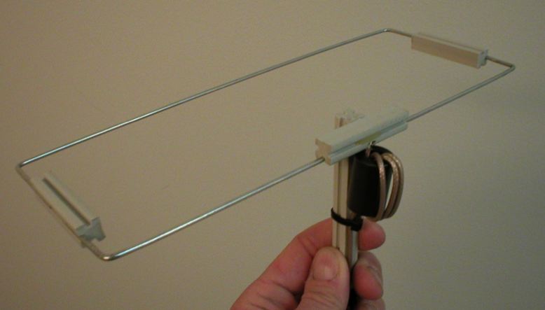
The completed antenna with its choke balun. In fact even with no balun the pattern seemed to be symmetrical so the balun is there more according to the textbooks than actual measured necessity.
Now it would be interesting to do a full scale version of it for its proper use - the short waves!
Ideas and feedback are most welcome. Mail to
Michael has a wonderful website at http://www.isy.liu.se/~mj/HAM/ANT where he has posted many fine antenna construction notes.