...listed in chronological order with newest message last.
Note: Click HERE to post an email to the MOXON Message Board
|
8/27/2003
You may already be aware of this, but if you are adding a 20m Moxon to a 17m Moxon severe interference will occur to the inside Moxon. At least this happens with 50 ohm coax feeds. I have not tried feeding the Moxon with ladder line. LB Cebik has come up with several ways to accomplish this. However, he recommends skipping a band for nested Moxon's (i.e. 12/17, 15/20, etc.) for best results. See http://www.cebik.com/mox1712.html. I have modeled all three versions, and I agree that the last one presented (stubbed array) yields the best results. The 50 ohm feed is at the inside Moxon with a 70 ohm 0.8 VF transmission line to the outside Moxon. I haven't come up with a practical method of accomplishing this with the wire (Black Widow) version as it would require a more complicated support system. Perhaps some ingenious builder can come up with a practical idea. If your group has figured this problem out, I would like to know the solution! I have modeled a nested 15/20m Moxon with separate feeds and still get poor results on the inner Moxon. This translates to about 1/2 the gain and 1/5 the f/b of a monoband Moxon. I would expect to see the same or worse on 17/20m. This is the one disadvantage to an otherwise excellent antenna.
73, Allen Baker, KG4JJH |
|||||||||||||||||||||||||||||||||||||||||||||||||||||||||||||||||||||||||||
| 8/27/2003
|
|||||||||||||||||||||||||||||||||||||||||||||||||||||||||||||||||||||||||||
|
8/27/2003
I have gotten emails on why we decided to use crappie poles for the antenna project instead of available 6 and 8 foot poles from antenna manufacturers.You might add the following to the webb site.
1) the crappie poles because they are tapered, they actually droop less than the pultruded poles offered by quad manufacturers.
2) The crappie poles weigh less than a pound each at 16 feet in length. This means a light weight pushup mast can support them and an economical rotor (radio shack) can turn the beam.
3) The crappie poles have much lower wind area for a given length. This is because they are tapered.
4) The crappie poles slip down nested to less than 46 inches down in length. This makes them great for portable use.
5) Economy. A sixteen foot crappie pole is $10.00 and a standard spreader would cost about $40.00 each for a single 16 foot with 3 sections. This means the difference of $40.00 for crappie pole spreaders for a Moxon versus $160.00 for standard spreaders. Or about $50.00 for a complete antenna. Shipping of the crappie poles is much cheaper.
6) Availability. Depending on your area of the country, crappie poles are readily available. If not you can arrange to get some through the Moxon project.
7) Stealth. With a coat of white household paint primer, and a bit of gray paint splatter, the moxon made with crappie poles is relatively inconspicuous. The color combo will vary depending on your area of the country and if you have trees, etc.
73's John kd6wd |
|||||||||||||||||||||||||||||||||||||||||||||||||||||||||||||||||||||||||||
| 08/29/2003
I visited your website concerning the Moxon. I
believe the antenna can be made using RG-58 coax to take advantage of the
velocity factor .66 verses .95. |
|||||||||||||||||||||||||||||||||||||||||||||||||||||||||||||||||||||||||||
| 09/01/2003
Yes this project is a lot of fun and its quite
rewarding to read from happy builders. |
|||||||||||||||||||||||||||||||||||||||||||||||||||||||||||||||||||||||||||
|
09/02/2003
We had more than a few Murphy's at a minimum yesterday. The temperature was well above a hundred here on the plateau. The plastic pole holder turned into a fiasco. The heat caused the plastic cutting boards to bend over a quarter of an inch end to end. We spend about 4 hours messing with them and add-ons to stiffen them. They ended up weighing more than the metal pole holders and do not appear to be worth the trouble for any ham to mess with. As an experiment Bob used a sledge hammer to beat flats into conduit. He then used a trailer hitch to increase the bend to 22 1/2 degrees. Total time for fabricating a bracket from raw material about 1 hour. Time on the plastics was about 3 hours. The plastics required a lot of special tools to fab. Hole saws, radial arm saw, 4 different drill sizes and two people to put them together. One version require a router. Total holes on the metal brackets was 10 and total holes on the plastic bracket to get it stiff enough was 48 and required a bunch of support screws for stiffeners. In conclusion the metal bracket is the cheapest and lowest hassle of any of them. ab0yy or Martin's setup appear to be the cheapest and easiest to fabricate out of something that is not metal. The fiber reinforced plastic panels are far to expensive (about 36 dollars per square foot) and are heavier than the metal bracket we now use. Plywood is more rigid and lighter.
Now to the 17/20 meter moxon. The original one was fabricated out of 3 sizes of Pvc sprinkler pipes. I used radio works kevlar-dacron 3/32 string to support it from a 3 foot high extension post above the mast bracket. I threaded 12 gauge wire thru the pipes and soldered 20 gauge wire to the end for the tails. This gave me a x-beam on 20 meters and a moxon on 17 meters. This setup was not too bad. I then added a short length of ladder line from the moxon feed point to the 20 meter feed point, though this was not perfect the swrs dropped to about 2 to 1 on both bands. I used 6 radio works type 34 chokes end to end attached to the coax near the feed point and this kept the feed line from radiating and I had no more rf in the shack at about 400 watts with my al811. Since I did not bother to try front to back with this setup ( I didn't have a rotor on the radio shack mast) I only could point it in one direction and just work stations. The originally one used 1/4 inch coax I am now using 1/2 inch 211 right now.
My conclusions:
1) Since the original design had the elements at angles to each other, there was minimum interaction between the two bands.
2) the pvc pipe allowed the 20 meter elements to average about 2" separation between the elements where they intersected.
3) The original 17 meter moxon was out of 20 gauge bare copper wire. I used the 16 gauge wire on what you guy's got so you could run well over 500 watts. According to w4rnl you can run a kilowatt on 18 gauge. Rather than fry an amp, I thought 16 gauge tinned would give a safe margin. This change in wire gauges caused more droop than my last 17 meter only moxon with 20 gauge bare copper and crappie poles.
4) The slop in the original pvc pipe version with 20 meters on it and this probably helped reduce interaction between the two bands. It sort of gave separation similar to that on a hexbeam.
5) I should have kept better records and taken pictures of the first version. This would have allowed me to give you guy's a better idea of what I had thrown together.
6) Tests with overlaying a moxon with an xbeam indicated that different styles of antennas could be on the same support structure.
7) Originally, I had hoped to get 12,17 and 20 (my favorite bands) on the same setup. When I saw the "Black widow setup", I made the assumption that with longer fishing poles, I could get this to fly. The intent was to use hexbeam layout for 12 meters, moxon layout for 17, and xbeam layout for 20 meters. This way a three band beam antenna for under 50 bucks, a group test (all you guys), and a group article for QST. I than proceed to search the net for Chinese manufacturers of poles. I found a couple of sources of poles up to 7 meters. A friend of mine ( who is in the import business) looked at some when he when to china, brought me back 5 of them and setup me up to get the first cases of 25 each. The first tests with 20 gauge on 17 meters using the crappie poles worked very well on my quad tower at about 40 feet, and that is when I started requesting you guy's to volunteer for this project.
8) Original 17/20 had a 100 feet of 1/4 inch feed line. I have no idea of what effect this had on the 17/20 meter setup 73's kd6wd |
|||||||||||||||||||||||||||||||||||||||||||||||||||||||||||||||||||||||||||
| 09/02/2003 Care and feeding of your moxon: If you plan to leave your moxon up as a permanent installation, the following is recommended: Protect the fiberglass poles with paint. I suggest using exterior house primer. Failure to do this will result in deterioration of the fiberglass. Instead of using tywraps at the wire junctions use a light gauge steel wire and a dab of epoxy. Seal up all coax connectors well. Water leaks in to the coax will give you a dummy load and not an antenna. Preparation for painting: disassemble each pole to its individual elements. Then using a fine steel wool or very fine sand paper sand each segment of the pole until it is dull in appearance. This will remove the light wax layer that exists and allow for good adhesion of the paint. Then reassemble the poles, extend them fully, and paint with a light layer of paint. I painted one set of mine white with house exterior primer, splattered them with a light gray, and they were all but invisible from the street. Safe placement of your moxon is important. So is common sense. Keep the doggone antenna away from the power lines to your house, and power lines to your neigbors house. This antenna plays like a champ at 20 feet with a hundred feet of rg58. So there are many options for mounting. Chimney mounts with a 10 ft mast and a rotor work well. Just use 4 straps instead of two for the chimney brackets. Phillystrand or dacron guys work great without detuning the antenna. So make sure that if the short push up mast should ever come down, it will fall on your property and clearly miss powerlines. If you have children or have children visit you, make sure that they cannot accidentally knock your mast over. This moxon has a wind area of less than 3 feet and is less than six pounds in weight, but should anything of even that light weight fall from 20 feet it can cause serious injury or even death. If you are new to ham radio, get another experienced ham to check things out for you.
73's kd6wd |
|||||||||||||||||||||||||||||||||||||||||||||||||||||||||||||||||||||||||||
|
10/19/2003
I thought I would drop you a line for the site. I built a moxon for 15m this weekend---works great. I used bamboo poles and #12 insulated copper stranded wire. The antenna is up about 35 feet and rotated with, what else, a radio shack rotor...
My first conatact was a G4 who gave me a 5-7 report...later in the day I worked 9J2BO in Zambia and C5Z in The Gambia. Infact, I have worked more DX into Africa with this antenna than I have in over 20 yrs of hamming. None of this would be half as impressive if it were not for the fact it was done with my FT-817 at 5 watts.
To say I am impressed is an under statement . I still have not figured out the fronto to back business yet but it is apparent...although strong sigs seam strong in any direction and every time I try to test a weak one QB messes up the test...nedd to get a local station and maybe do some tests.
Mant thanks for the site. I appreciate any comments concerning the front to back tests.
cheers,
scott VA3ZW Rockland, Ontario |
|||||||||||||||||||||||||||||||||||||||||||||||||||||||||||||||||||||||||||
| 11/28/2003
I built a Moxon rectangle beam following the
advice on your Murray State |
|||||||||||||||||||||||||||||||||||||||||||||||||||||||||||||||||||||||||||
| 12/07/2003
For some months I have been reading about the
Moxon and of course found |
|||||||||||||||||||||||||||||||||||||||||||||||||||||||||||||||||||||||||||
|
03/04/2004
Assuming you want to build a coax element MOXON with a design center frequency of 7.260mhz:
Driven Elements = 650 / 7.260 = 89.532' / 4 = 22.382' cut (2) pieces of coax to this length. When you measure these lengths with the 259B they will be further reduced in size due to resonance.
The Reflector Element will be 5% longer than the total length of the (2) Driven Elements. In other words, lets say you end up with each Driven Element being 22' long. This equals 44' total x 1.05% = 46.2' Reflector cut length.
Each Driven Element will bend to form the tail. Once again, assuming a measured element length of 22'. Only 30% of the element needs to be bent to form the tail. So, 22' * .30% = 6.6'. Each tail section on the Driven elements will be 6.6' long. Leaving 15.4' of each Driven Element for radiation.
The Reflector Element will be 30.8' straight across and each tail will be 7.7'. This totals 46.2'.
Driven Element to Reflector Element spacing should be between .20% and .15% of a wave length at the design frequency. For our example, assuming a design frequency of 7.260, 984 / 7.260 = 135.537' * .20% = 27.107' (way to wide) so, 135.537' * .15% = 20.3' (still way to wide). As you can see the spacing between the DE and RE is something that we cannot do anything about it if we are to have a reasonable amount of Front to Back.
If you use the 9' that N5GLR used you will end up with an antenna that exhibits a hell of a lot of forward gain but the F/B ratio will suffer.
Is that a bad thing? Not necessarily, if you live in the center of the USA like I do, then maybe you want to hear whats going on out West when you have the antenna pointed East.
In any case the antenna will out perform any Hex or "X" beam out there, and don't forget, the entire array will be 30% smaller than its AWG brother.
I would build one, but my total air time on 40m is 2hrs. per week and I use the Sterba Curtain for that. Most of my time is spent on 17m and 75m.
Have fun Steve, and keep us all up to date on your progress.
|
|||||||||||||||||||||||||||||||||||||||||||||||||||||||||||||||||||||||||||
|
03/20/2004==>LESLIE A. MOXON, G6XN, SK Leslie A. "Les" Moxon, G6XN, of Surrey, England, died March 3. He was 95 and among the oldest Amateur Radio operators in the UK. Licensed in 1928, Moxon was well-known among the amateur community for his writings on antennas, in particular his 1982 book HF Antennas for All Locations, now in its second edition. ARRL antenna specialist Dean Straw, N6BV, called Moxon a "radio pioneer" and said he'd been a fan of his work for years. "His insights into the effects of terrain were one of the factors that got me interested years ago in this aspect of HF radio work," Straw said. During World War II Moxon was involved in top-secret work to develop radar. He worked for the government as a radio specialist after the war, retiring in 1969. ARRL CEO David Sumner, K1ZZ, said Moxon's book "set the standard for practical antenna books and remains a classic." Moxon's son, David, recalls that his father's gardens grew antennas the way others grew plants and shrubs, and a new antenna design was always taking shape. "He always liked to live on the top of a hill--good for propagation of radio waves," he said. "And when moving to their final house in Hindhead, real estate agents were bemused to be asked about 'the long path to Australia.'" Moxon authored a July 1952 QST article, "Two-Element Driven Arrays." Several other of his articles appeared during the 1970s and 1980s in Ham Radio magazine. "A 6 Meter Moxon Antenna" by Allen Baker, KG4JJH, is among the antenna articles featured in April 2004 QST. In later years, Moxon developed an interest in theology, and he was not active on the air in the months prior to his death. A service was held March 10. Survivors include his wife Nancy and his son. ------------- Steven Hammer K6SGH email: k6sgh@cox.net website: www.k6sgh.com everything is cheaper in free space |
|||||||||||||||||||||||||||||||||||||||||||||||||||||||||||||||||||||||||||
| 04/05/2004
It's nice to read some articles about the moxon
antennas on your website ... |
|||||||||||||||||||||||||||||||||||||||||||||||||||||||||||||||||||||||||||
|
04/07/2004
Hi there. I got all of your emails off of the moxon website. I'm a 21 year old college student making the moxon antenna, and I was wondering if you could answer a question...
I build the 20 mtr moxon using a 1:1 balun and, much to my dismay, when I used the exact dimensions that the moxon generator gave me, the driven element was at a 1:1 SWR about 600 hz below the frequency I typed into the generator (13.700 instead of 14.300). I had to shorten the driven element to obtain a 1:1.
Now, the question... Do I keep the reflector at the length that the moxon generator gave me, or do I shorten the reflector to the length that would correspond to the "shortened" driven element. If I did the latter, the frequency that the antenna would correspond to, using the moxon generator, would be 15.070. Keep in mind that I shortened the driven element to resonate at 14.300, and it is shorter than the dimension the moxon generator gave me :(
I am confused. If anyone has an answer, it would be much appreciated.
thank you,
Garrett Ensign |
|||||||||||||||||||||||||||||||||||||||||||||||||||||||||||||||||||||||||||
|
04/07/2004
Hi Garrett,
Don't be concerned with making an error in calculations, at least you didn't have to add wire.:-)
Using the MoxGen software type in the frequency 14.300 and the ga. wire that you are using, the numbers that appear will be your new wire lengths.
The reflector element will always be about 5% longer (lower in frequency) than the total length of both driven elements. Where as director element will always be about 5% shorter (higher in frequency) than the total length of both driven elements.
If I can be of further help, let me know.
|
|||||||||||||||||||||||||||||||||||||||||||||||||||||||||||||||||||||||||||
|
04/09/2004
Garrett,
I had the same problem when building a 15m Moxon using insulated wire. The actual resonant frequency was considerably lower than that predicted by Moxgen. Here's what I did to solve the problem:
Final Length = (Measured Resonant Frequency) / (Desired Resonant Frequency) X Current Element Length
Do this calculation for all dimensions of the Moxon (A, B, C, & D) and then trim your elements and spacers to the Final Length.
For example: If the Measured Resonant Frequency = 13.7 MHz and the Desired Resonant Frequency = 14.3 MHz Lets say A = 301", B = 46", C = 7.5", and D = 56" 13.7/14.3 = 0.95804 A Final Length = 0.95804 x 301 = 288.37", so trim (301 - 288.37) = 12.63" from A B Final Length = 0.95804 x 46" = 44.07", so trim (46 - 44.07) = 1.93" from B C Final Length = 0.95804 x 7.5" = 7.185", so trim (7.5 - 7.185) = 0.315" from C D Final Length = 0.95804 x 56" = 53.65", so trim (56 - 53.65) = 2.35" from D
Good luck, and I hope this helps.
73, Allen, KG4JJH |
|||||||||||||||||||||||||||||||||||||||||||||||||||||||||||||||||||||||||||
| 04/09/2004 Garrett... I feel your pain-please go to |
|||||||||||||||||||||||||||||||||||||||||||||||||||||||||||||||||||||||||||
|
04/10/2004
Hi Garrett (and all you moxon fans)...
I have built a number of "moxens" for various bands with all sorts of wire / balun configurations. I have one piece of solid advice, Get yourself an antenna anayser - BUY, BORROW, BEG or STEAL !! . It is suprising ( well maybe not ) just how things change with wire types /coatings etc..Then if you start multi banding its even more fun !! - The moxgen is a good guidline but as they say over here, " the proof of the pudding is in the eating" hi hi . Enjoy desert and keep coming back for more.
Love my moxon
73 de Phil g0wsp |
|||||||||||||||||||||||||||||||||||||||||||||||||||||||||||||||||||||||||||
|
04/10/2004
Hi Garrett,
You said that you are in college. I recommend that you go down to the campus book store and pick a book titled "Grob Basic Electronics". The sections that may interest you have to do with capacitance, Inductance, electromagnetic induction, inductive and capacitive reactance's. Its a good basic book.
Like one of the previous replies suggested, Beg, Borrow or Buy an MFJ 259B antenna Analyzer, this unit will tell you exactly what the antenna is doing and how to correct any faults. You can buy the unit for $200 at ham fests or look on Ebay....there is one there for sale now under "Meters".
One solution to your situation is to not use pvc covered wire at all. You can use 18ga copper clad steel wire, this wire is available from "The Wireman" and is very inexpensive.
One other note; it is necessary to install a 50ohm balanced to 50ohm unbalanced current balun at the feed point (from Radio Works). Failure not to use this device will result in an electrical imbalance of the antennas electrical radiating field. In other words, the entire shield of the coax, all the way down to your rig, will act as the other half of the antenna.
When checking the SWR, if possible, check it at the antenna, not at the other end of your coax feed line. If it is not practical to check the SWR at the antenna, cut a piece of feed line that is 1/2 wave length long at your design frequency. Using the latter method, you will see the same numbers just as though you were testing right at the antenna.
Take your time, building antennas is fun, its not a mystery and its darn sure not rocket science.
We are all here to help, so keep the emails coming.
|
|||||||||||||||||||||||||||||||||||||||||||||||||||||||||||||||||||||||||||
|
04/10/2004
Hello All,
Antenna building weather is here, and we all know what that means.
In about two weeks I will have a 40m 2 element coaxial square up and running. The entire beam will weigh less that 10lbs on a 30' pushup pole and rotated with a tv rotor. The turning radius will be 16'-6".
Unfortunately I will not be able to build the antenna with the optimum spacing for a good front to back, but it will have a heck of a lot of forward gain.
I will keep the list up to date on the final construction details and performance.
From reading the list, I notice that a few of you are concerned about droopy elements.
Extend the mast 24" to 30" above the hub, put a PVC cap on the top along with an "eye bolt". I use 3/16" Dacron lines going out to 2 places on each pole....no runs no droops no errors.
I personally do not recommend the use of PVC for a mast. You would do better to use aluminum electrical conduit.
Through the fall and winter months my fully rotatable (at 30') 17m linear loaded coaxial extended double zepp has performed very well when compared to my Sterba Curtain.
This fall I will be taking down the 40m coaxial beam and constructing a fully rotatable N0KHQ 80/75m coaxial dipole, turning radius 16'-6".
All of my designs are slanted toward those ham radio operators that, 1. do not have the room to erect full size AWG antennas, 2. Do not have a hefty tower and a hefty rotor, and most importantly, 3. Cheap. :-)
Thanks once again Don for the nice Message Board.
|
|||||||||||||||||||||||||||||||||||||||||||||||||||||||||||||||||||||||||||
|
04/12/2004 hello all: |
|||||||||||||||||||||||||||||||||||||||||||||||||||||||||||||||||||||||||||
|
04/13/2004 Hello, |
|||||||||||||||||||||||||||||||||||||||||||||||||||||||||||||||||||||||||||
|
04/14/2004 I
have found a reliable source for crappie poles. somewhat better Our group people should call him at 931-394-3052, ask for Wendell and K6SGH |
|||||||||||||||||||||||||||||||||||||||||||||||||||||||||||||||||||||||||||
|
04/22/04 Hello to everyone... Click
HERE to
view a small PDF-File with some pictures of my solution of the |
|||||||||||||||||||||||||||||||||||||||||||||||||||||||||||||||||||||||||||
|
05/02/04
For those of you trying to nest moxon antennas. I have the following suggestions:
1) Keep the planes of the MOXON separated with considerations given with respect to the angle of radiation. 73's (yes I am a young guy and only send 73 on cw! HI HI) kd6wd |
|||||||||||||||||||||||||||||||||||||||||||||||||||||||||||||||||||||||||||
|
05/24/04 Hello all...
Well, I took down my 15m Moxon today after a
Canadian Fall, Winter and Spring. It was in surprisingly good shape and
still in tune. The weather had, however, distorted the plywood support
plate where the bamboo rods met and the bamboo itself was a bit more
'droopier' than before. That aside, however, it was A-1. Not bad for 15$
worth of materials.
I plan to use a new design this summer--maybe an all aluminum moxon if I can manage it.
Cheers
Scott VA3ZW |
|||||||||||||||||||||||||||||||||||||||||||||||||||||||||||||||||||||||||||
|
06/11/04
Hi all
What a great site you have going here i am very intersted is the moxon antenna,I find it hard to find spreaders or fishing poles long enough for a 20 meter moxon.I live in CANADA and was wondering what others are using for light weight spreaders, and where to buy them crappie poles sound good but i bet they are not shipable.:(
Thank you Corey ve1kco
Webmaster's comments: Visit
www.catfishsupplyco.com . One of the MOXON participants has
negotiated a price for poles if you
purchase 4 poles at a time. Call him at 931-394-3052, ask for Wendell and |
|||||||||||||||||||||||||||||||||||||||||||||||||||||||||||||||||||||||||||
|
07/04/04 Hello all,
|
|||||||||||||||||||||||||||||||||||||||||||||||||||||||||||||||||||||||||||
|
07/07/04
Wow! I just finished my first Moxon rectangle
yesterday evening and will post photos shortly. It's of conventional
construction using fiberglass crappie poles and #16 AWG antenna wire. I
used a 12" square of acrylic and a PVC plumbing fixture called a companion
flange for the hub and mounted the antenna on a 5 foot piece of schedule 80
PVC plumbing pipe strapped to a chimney mounted TV mast. I'll soon install
a rotator. |
|||||||||||||||||||||||||||||||||||||||||||||||||||||||||||||||||||||||||||
|
07/12/04
Hi again, |
|||||||||||||||||||||||||||||||||||||||||||||||||||||||||||||||||||||||||||
|
07/17/04
Hello all... OK, I'm convinced to give the Moxon a go...skeeters or not, here in the hot & humid Arkansas Delta. I've been thinking about a creative way to use 1/2 of a two-piece 2 el cubical quad boomless aluminum spider I acquired recently with some type of "X-Hex-Mox" type design for 20M. Since the 45 degree angle would put the wire a little further up in the air, I would think that could be a bit of an advantage with my small push-up mast. But then again, is this likely to be tricky since the quad spider is configured for 'square,' vs. rectangular configuration?
Another couple of questions: Has anyone tried this technique before, and what considerations will I likely encounter? And since I'm 99% CW, what frequency should I begin with (w/MoxGen on 20M) to provide advantageous SWR and overall performance in the low end of the band? I was thinking about using adjustments tweaked for 14.025MHz, but perhaps the antenna is more broad-banded...
BTW, I've been a ham for 42 years and am amazed that I only recently "heard of" these designs...I've yet to actually hear anyone using a Moxon, but the testimonials are convincing. Is it a commercial antenna manufacturer conspiracy? ;-)
Tks/73/DX,
Ron, K5XK (See W3CRR's response below)
|
|||||||||||||||||||||||||||||||||||||||||||||||||||||||||||||||||||||||||||
|
07/18/04
Hi Ron,
As for its bandwidth -- I, like you, am primarily a CW guy. I cut the first Moxon, however, for 14.225 in order to "show it off" to my buddies on the Collins Collectors' Association net (14.263 SSB). I was astounded to discover, however, that my 'phone-tuned Moxon, had an SWR of less than 1.3:1 over the whole 20 meter band -- better than my modeling software had predicted. If you cut your Moxon for 14.175, erect it at least 20-feet off the ground and keep metal away from it (especially out of the "rectangle", you'll have a beautifully "flat" response. Of course, like any Yagi-derived design, your forward gain will be higher below the resonant frequency at the expense of F/B ratio and vice-versa, but I've found this antenna to perform well in both aspects throughout the band.
|
|||||||||||||||||||||||||||||||||||||||||||||||||||||||||||||||||||||||||||
|
08/26/04
Hello all... I was curious about the basic electrical design of the Moxon, and converted your construction dimensions to simpler wavelength fractions. In this way I could get a better minds eye view of the antenna as an electrical device.
My interest is to perhaps use a Moxon on 6 Meters for mountaintop contesting. While (by your gain figures) it will probably have a couple dB's less gain than the 2 element Cubical Quad I now use (2 elements at .12 wavelength spacing) it will be physically smaller and present a better overall mechanical configuration with my other beams on 2 Meters as well as 135, 70, and 23 centimeters.
Your "Performance" reports seem somewhat anecdotal. Has anyone built one of these for the VHF or UHF spectrum? This would of course be a way to obtain real gain figures in dBm.
73! de John "KF6GDJ" (see response below) |
|||||||||||||||||||||||||||||||||||||||||||||||||||||||||||||||||||||||||||
|
08/26/04
John,
I have had a lot of fun and great success with the 6m Moxon. During my last camping trip over the July 4th holidays, I logged Portugal using 100w ssb with the antenna on a painter pole at 15 feet. The antenna is mechanically robust as it is constructed of 6063-T832 drawn aluminum tubing, structural aluminum channel, solid fiberglass rod insulators, polypropylene tubing clamps, and stainless steel U-bolts/hardware. Overall dimensions (centerline to centerline) are approximately 84.5" x 31.5" and the total weight is 8.5 pounds. As to the antenna's gain and other characteristics, I have no hard information other than what I have modeled in EZNEC and measured on my MFJ analyzer.
At 15 feet elevation, the horizontally polarized version has the following modeled specs at 50.5 MHz:
At 30 feet elevation:
For more technical information, go to LB
Cebik's site at
http://www.cebik.com/6m.html. I think you will find this antenna to
be great for portable use. So, in case you are interested, I am attaching
the drawings &
EZNEC files to this email. Please keep Don and the group
informed of your progress should you decide to build one. Good Luck!
73, Allen, KG4JJH |
|||||||||||||||||||||||||||||||||||||||||||||||||||||||||||||||||||||||||||
|
10/11/04 Hello,
I want to put a dual-fire 40M moxon in the attic, made of wire but I'm a whisker short on space. Traditional Moxon designs show that I need over 15 meters width - but I only have about 13. By the way, by "dual-fire", I mean feeding coax to both elements and switching them in the shack - this will give me some West and East gain (North-South attic).
To shorten the Moxon, I am firstly about to test out tomorrow morning a home-brew shortened di-pole, using a couple of home-brew coils I made up after dinner tonight. Once tuned for about 7.1 Mhz, I will make up a matching dipole and proceed to the attic to construct my Moxon.
Do you think I'm off at a tangent or will I get some results on this one? I'm worried about the dimensions too. I feel some experiementing might be in order.
So, rather than experiement blind, I thought I would share this with you and ask if anyone else had tried to "shorten" a Moxon in this fashion and what their results were..?.
I'll pop back in a few days.
Kind regards,
_____________________________________________
Callum McCormick M0MCX p.s.
I love
detailing my projects by the way and have already taken pictures of the
coils and stuff I'm using. Right now I'm just wondering whereabouts
along the dipole I should mount them. I think about 66% sounds neat.
The below link leads to some pictures of my current project which is almost finished. With the CQWW contest coming up, I need some gain on 40, hence the Moxon "project" which sounds better than a straight forward 2 ele beam, particularly with the nulling properties.
http://www.mccormick.uk.com/towerproject/
|
|||||||||||||||||||||||||||||||||||||||||||||||||||||||||||||||||||||||||||
|
10/11/04
The 'Dual Fire' concept that Callum refers to, I believe, is what I did with
the 40 Meter Moxon in Boston. It is possible to electrically switch the 40
meter Moxon. You get rid of the reflector by making it into a driven
element. Thus you have two driven elements in the Moxon rectangle. You set
up a relay to feed either. The length of coax between the remote relay and
the center of either driven element is cut so as to introduce the reactive
component needed to lower the resonant frequency of the unfed element
sufficiently so as to cause it to behave as a reflector. A tricky operation.
Within an attic it is likely to not exhibit performance levels which would
justify the effort of constructing and tuning it. |
|||||||||||||||||||||||||||||||||||||||||||||||||||||||||||||||||||||||||||
|
10/12/04 During the last six months I have made three Moxon antenna's and following the formula exactly, all of them worked perfectly on completion, without any further adjustment. They were made to operate on 2 meters, 4 meters, and 6 meters and each one has an SWR of 1:2:1 or 1:3:1. The first one was made for 4 meters, a band not available in the USA and on testing it I was astounded to find that the SWR was so low. I expected to have to make adjustments, but none were required. The biggest problem was having to find ways of fitting the different sizes of aluminum tubes that I have to make the antenna and then find the appropriate Jubilee or circlip clips to hold the 3/4" and 5/8" tubes together and then fix it to a mast. I was also able to adjust the antenna so that it could be used in the vertical or horizontal position. After making it and buying a small 4 meter FM rig I found that operators on the band were as rare as hens teeth so I sold the rig and the antenna to a fella who lived 900 ft.ASL. The 6 meter Moxon has yet to be used, the only operator I have heard was a mobile who answered a call from an Italian station and their contact lasted about 45 seconds! This antenna was made with 10 mm aluminum tube and the problem on this model was fitting the 1/4" aluminum rod for the corners into the 10 mm tubes and making a tight fit as there are no clips available which are small enough to do the job. This was done by drilling the correct size hole into plastic washers that I made and then squeezing them over the slotted tube and the washers held the rod and the tube together very tightly. The next project will be a Moxon for 10 meters but there is no rush to get started as the band will not be available for any decent DX until about 2008. 73, Mel G0GQK |
|||||||||||||||||||||||||||||||||||||||||||||||||||||||||||||||||||||||||||
|
11/06/04
Hello all.. There are some great variations of the moxon theme on the site, especially "Bills Baby" W1ZY `s 40mtr beast ! - well done guys. My multi MOXON was still going strong up till 12 months ago - it was a dreadful night - blowing a real hoolie as we say over here, the xyl and I were off to V44 the following day , so we decided to take the MOXON down, to cut a long story short a big gust of wind blew up and took us all to the ground !!! - guess what ?, the MOXON broke my fall - and YES !! - I broke the MOXON. - Boo Hoo !!! Not to be deterred we licked our wounds in St.Kitts and I strung up a 20mtr "mini mox" to work QRP with my faithful FT817 ( Incidentally - there are some great guys over there - Carl V44NK - Terry V44KBP and Earl V44NEF were extremely helpful and hospitable). Holiday over, it was back to the workshop in "G" land where we resurrected the remains of the "MULTI - MOX" but this time as a single bander for 20 mtrs, to try and evaluate the differences. Obviously without a "reference" antenna it is a bit of a meaningless exercise - but I do have a good friend G0MUR who lives just down the way from me - he works the world on his G5RV and we have made many comparisons over the years, so he is my reference antenna. Again with cycle conditions changing we can only be subjective - but yes - I think the single bander does have the edge. In the past 11 months the DXCC has risen 6 to 295 countries ( the latest being XX9,YV0D,FO/A,FO/M,V63 and V73), all having been "MOX`d". DONT THINK IT - DO IT !!!. Cheers to all and keep up the good work. Phil G0WSP |
|||||||||||||||||||||||||||||||||||||||||||||||||||||||||||||||||||||||||||
|
11/09/04
Hi to all.... I am contemplating building a moxon like W3CCR's moxon (20 mtr), and also a 17 mtr moxon in the same fashion. Both will be on the same mast using the same rotor, but separate coax feedlines. I figure the 17 mtr moxon will be about 3-4 ft. above the 20 mtr moxon. Will I get any interaction or degraded performance from either, or should I install on two separate masts, say,75 ft. from each other? I wanted to get some input before I start building so my efforts aren't futile and waste valueble time before the snow flies here. Thanks in advance. Paul AD3G (see two replies to Paul's question below) |
|||||||||||||||||||||||||||||||||||||||||||||||||||||||||||||||||||||||||||
|
11/09/04
Hi Paul, |
|||||||||||||||||||||||||||||||||||||||||||||||||||||||||||||||||||||||||||
|
11/10/04 Paul,
I have looked at stacking Moxons in an earlier attempt to get two or more bands on the same mast. 20/17m modeling results are listed below. In general, the antennas will become detuned when separated by 5 feet, especially for 17m. Also, the 17m gain is down 1 dBi and the f/b ratio is less than one half that of a monoband Moxon. If you can live with these numbers and tune both bands back into resonance you will have a working antenna, but not one that retains the monoband Moxon characteristics. 20/17m antennas vertically separated by 30 feet or more require no modifications to stack and come closer to monoband figures.
Until reading LB Cebik's article on Moxon Nesting I
had problems multibanding the Moxon (http://www.cebik.com/mox1712.html).
Cebik's advice is to skip a band when nesting (i.e. 10/15m, 12/17m,
15/20m, etc.). After many hours of EZNEC modeling I came away with a "buildable"
dual band wire Moxon for 12/17m that retains the characteristics of
the monoband version. Since then, I have successfully built and used
the antenna with excellent results. The elements are at the same
elevation with one common 50 ohm feed. A construction article was
submitted to QST and will be published in the future.
I hope this answers some of your questions. Good Luck!
73, Allen, KG4JJH Stacking Moxon Rectangles KG4JJH
1. Moxgen generated elements (20m = 1.5” alum, 17m = 1” alum). EZNEC model for each antenna individually:
2. EZNEC model for both antennas with 5 ft. separation:
3. EZNEC model for both antennas with 20 ft. separation:
4. EZNEC model for both antennas with 30 ft. separation:
Conclusions: 1. Compared to monoband Moxons, at 5 ft. separation the resonance of the 20m Moxon shifts down 100 KHz, gain & F/B are OK. The resonance of the 17m Moxon shifts up 600 KHz, gain is down –1 dBi, & F/B is down 16.35 dB. If you can live with the reduced gain and F/B, change the dimensions of the both antennas to move resonance into the bands. Multiply each dimension of the 20m Moxon by 0.99293, and each dimension of the 17m Moxon by 1.02936.
After this adjustment the EZNEC model for both antennas with 5 ft. separation looks like this:
2. Mount the 17m Moxon 30 ft. higher than the 20m Moxon. 20m figures are the same as monobander. 17m gain is up 1.4 dBi (due to increased elevation) but f/b is down about 10 dB. |
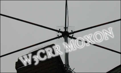 For
the most part, construction of my Moxon is conventional. I utilized 16-foot
crappie poles as spreaders and 16 gauge stranded antenna wire as elements.
The wire's attached to the lightly sanded spreaders with heavy-duty
electrician's UV-resistant cable ties (a Home Depot item) and a wrapping of
premium Scotch 88 electrical tape. The element spacers are small diameter
lengths of PCV pipe. Here's a helpful hint regarding them, by the way. Drill
a single hole on each end and thread your antenna wire through these. In
other words, don't use the full diameter of the pipe when attaching the
wire. If you do, the resultant loop of wire can de-tune the antenna. Of
course, using a flat spacer - like a piece of acrylic sheet - would do the
trick and look better, too. That'll be an "upgrade" on my antenna.
For
the most part, construction of my Moxon is conventional. I utilized 16-foot
crappie poles as spreaders and 16 gauge stranded antenna wire as elements.
The wire's attached to the lightly sanded spreaders with heavy-duty
electrician's UV-resistant cable ties (a Home Depot item) and a wrapping of
premium Scotch 88 electrical tape. The element spacers are small diameter
lengths of PCV pipe. Here's a helpful hint regarding them, by the way. Drill
a single hole on each end and thread your antenna wire through these. In
other words, don't use the full diameter of the pipe when attaching the
wire. If you do, the resultant loop of wire can de-tune the antenna. Of
course, using a flat spacer - like a piece of acrylic sheet - would do the
trick and look better, too. That'll be an "upgrade" on my antenna.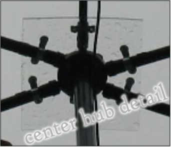 The
antenna's hub/mounting plate is a bit unusual. It's a 12-inch square
clear ¼" acrylic sheet with a 1-1/2-inch PVC plumber's "socket flange"
bolted to the bottom. The antenna is then mounted on a mating 5-foot length
of Schedule 80 PVC pipe to separate it from the steel TV mast upon which it
is ultimately lashed (see photo at right). It is imperative that no large
metal pieces bisect the rectangle. All metal hardware on my antenna is
stainless steel and kept to a minimum. For instance, the spreaders are
attached to the mounting plate with PVC conduit straps rather than the usual
metal ones. That may be overkill, but I'm comfortable.
The
antenna's hub/mounting plate is a bit unusual. It's a 12-inch square
clear ¼" acrylic sheet with a 1-1/2-inch PVC plumber's "socket flange"
bolted to the bottom. The antenna is then mounted on a mating 5-foot length
of Schedule 80 PVC pipe to separate it from the steel TV mast upon which it
is ultimately lashed (see photo at right). It is imperative that no large
metal pieces bisect the rectangle. All metal hardware on my antenna is
stainless steel and kept to a minimum. For instance, the spreaders are
attached to the mounting plate with PVC conduit straps rather than the usual
metal ones. That may be overkill, but I'm comfortable.
Note: Click HERE to post an email to the MOXON Message Board